

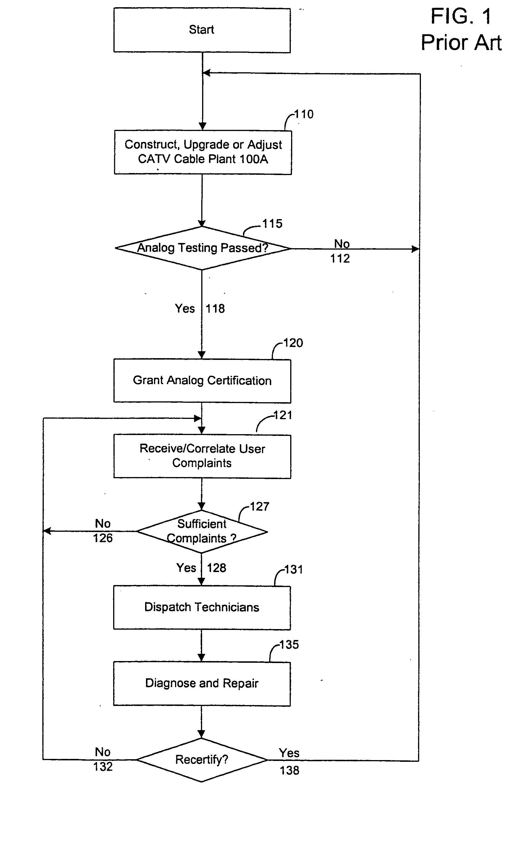
System and method for digitally monitoring a cable plant
a technology of digital monitoring and cable plant, which is applied in the field of certification and monitoring of cable system or plant, can solve the problems of reducing the service life of the cable system
- Summary
- Abstract
- Description
- Claims
- Application Information
AI Technical Summary
Benefits of technology
Problems solved by technology
Method used
Image

Examples
Embodiment Construction
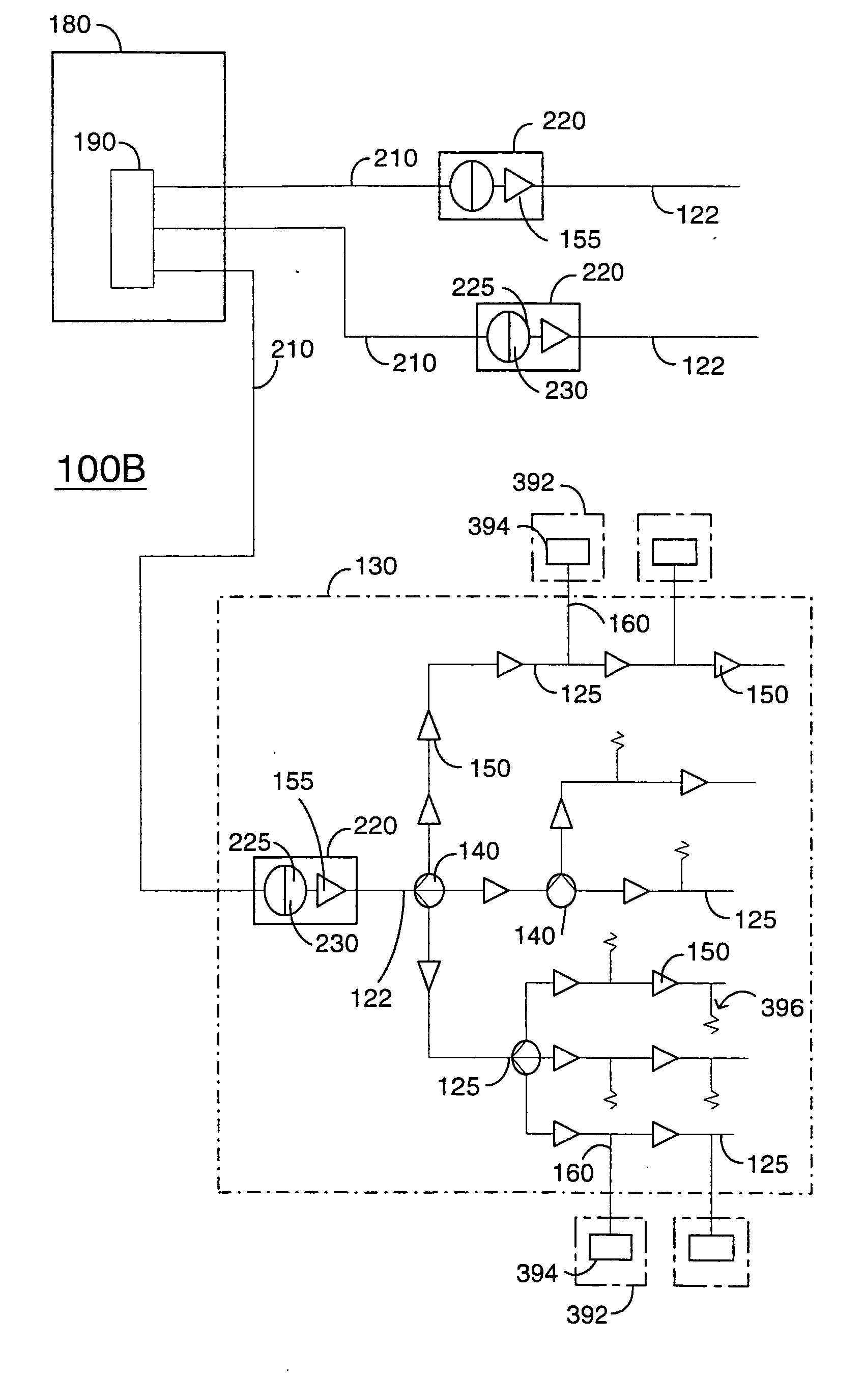
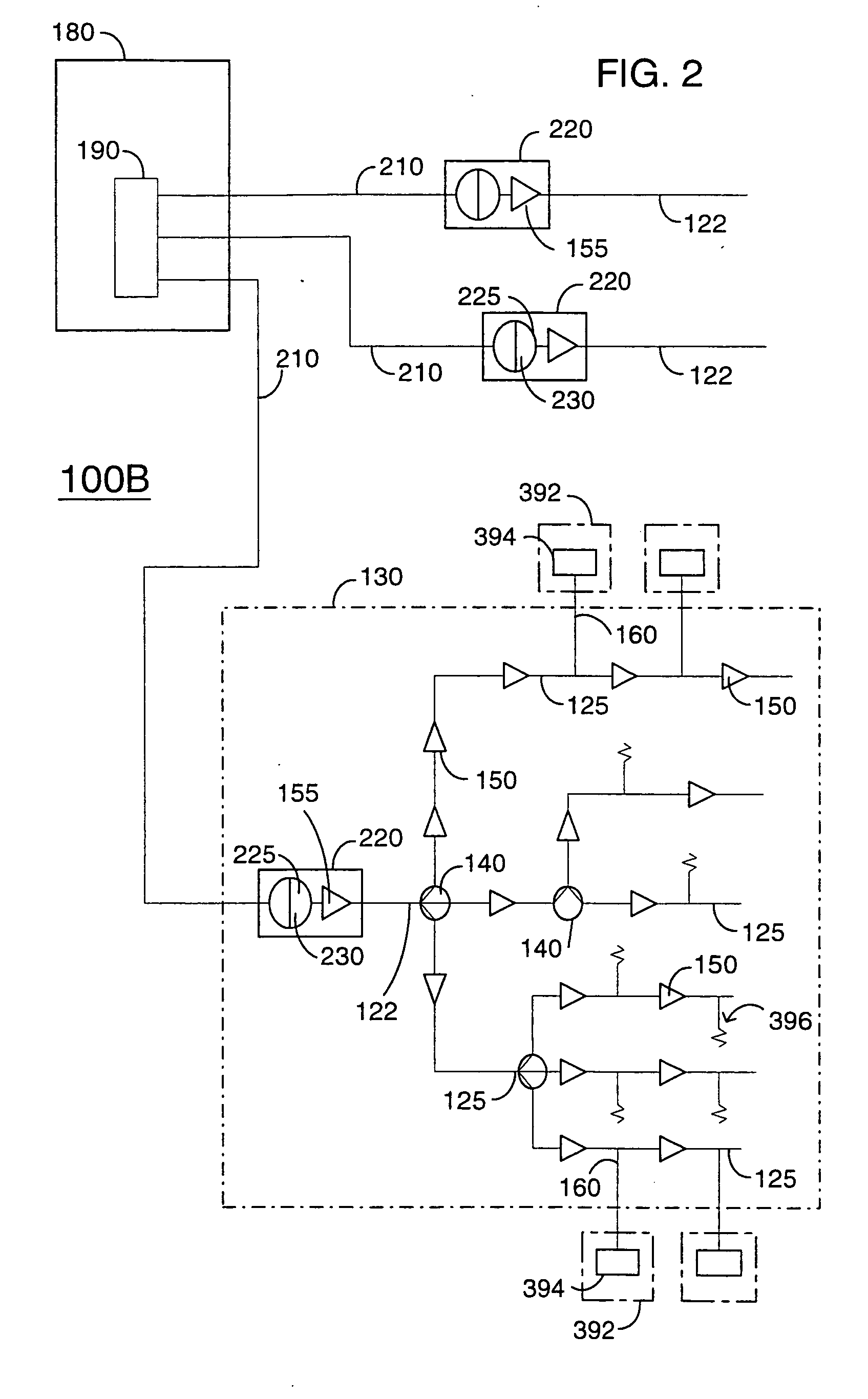
[0022]FIG. 2 is a block diagram illustrating the interconnectivity of some components of an HFC CATV cable plant 100B capable of interactive data service. This diagram is greatly simplified for ease of explanation. HFC cable plant 100B encompasses a headend 180 containing a cable modem termination system (CMTS) 190 coupled to one end of each of three fiber optic trunk cables 210. Each trunk cable 210 at its other end is coupled to a respective one of three optical network units 220. Although FIG. 2 shows three trunk cables 210 coupling to termination system 190, other configurations having a larger or small number of coupled trunk cables 210 are possible. Similarly, some embodiments in accordance with the invention have multiple termination systems 190.
[0023] Each optical network unit 220 couples one fiber optic trunk 210 to one coaxial cable run 122, and thus serves as the initiation point of local distribution networks, one of which, network 130, is shown in some detail for illus...
PUM
 Abstract
Description
Claims
Application Information