Solar cell module

a solar cell module and module technology, applied in the field of solar cell modules, can solve the problems of reducing the adhesion, increasing the melting point reducing the adhesion, so as to improve the moisture resistance of the solar cell module, and prevent the electrodes from being deteriorated.

Inactive Publication Date: 2005-09-15
PANASONIC INTELLECTUAL PROPERTY MANAGEMENT CO LTD
View PDF12 Cites 174 Cited by
  • Summary
  • Abstract
  • Description
  • Claims
  • Application Information

AI Technical Summary

Benefits of technology

[0033] In the above solar cell module, the water vapor transmission rate of the rear surface protective member is preferably 0.1 g / m2·24 hrs (40° C., 90%) or less and the percentage of epoxy content in the thermosetting resin is 80 vol. % or more. In the case where the water vapor transmission rate of the rear surface protective member is 0.1 g / m2·24 hrs (40° C., 90%) or less and the thermosetting resin contains 80 vol. % or more epoxy resin, it is possible to easily prevent the electrodes from being deteriorated resulting from hydrolyzed thermosetting resin. Therefore the moisture resistance of the solar cell module can be improved. Note that the water vapor transmission rate of 0.1 g / m2·24 hrs (40° C., 90%) or less means an amount of water vapor that permeates through the rear surface protective member is 0.1 g / m2 or less after a 24-hour water vapor transmission test conducted at a temperature of 40° C. and a humidity of 90%.
[0034] In the above solar cell module, the water vapor transmission rate of the rear surface protective member is preferably 0.02 g / m2·24 hrs (40° C., 90%) or less and the percentage of epoxy content in the thermosetting resin is 70 vol. % or more. In the case where the water vapor transmission rate of the rear surface protective member is 0.02 g / m2·24 hrs (40° C., 90%) or less and the thermosetting resin contains 70 vol. % or more epoxy resin, it is possible to easily prevent the electrodes from being deteriorated resulting from hydrolyzed thermosetting resin. Therefore the moisture resistance of the solar cell module can be improved. Note that the water vapor transmission rate of 0.02 g / m2·24 hrs (40° C., 90%) or less means an amount of water vapor that permeates through the rear surface protective member is 0.02 g / m2 or less after a 24-hour water vapor transmission test conducted at a temperature of 40° C. and a humidity of 90%.
[0035] In the above solar cell module, it is preferable that the rear surface protective member includes an insulation layer made of either silicon oxide or metal oxide. The insulation layer made of either silicon oxide or metal oxide, which has a low water vapor transmission rate, contributes to reduced water vapor transmission rate of the rear surface protective member. In the case where the insulation layer is used for the rear surface protective member, insulation failure between the connecting tab and the rear surface protective member does not occur in a solar cell module in which a plurality of solar cell elements are connected to each other by connecting tabs. Therefore, the improvement of the moisture resistance can be obtained while yield reduction caused by the insulation failure can be prevented.
[0036] In the above solar cell module, it is preferable that the rear surface protective member includes resin materials but not metal materials. Accordingly, insulation failure occurring between solder for connecting the connecting tabs to the solar cell elements and the rear surface protective member is reliably prevented in a solar cell module in which a plurality of solar cell elements are connected to each other by connecting tabs.
[0037] In the above solar cell module, the front surface member contains sodium and a sodium blocking layer for preventing sodium permeation is provided between the front surface member and the solar cell element. Accordingly, even when sodium is leached out from the member containing sodium to water permeating into the solar cell module and the sodium-containing water diffuses in the solar cell module, the sodium blocking layer prevents sodium from reaching the solar cell elements. In the case of the solar cell elements including a p-type semiconductor layer, activity of p-type impurities in the p-type semiconductor is not discouraged by the sodium. As a result, output-characteristics reduction of the solar cell module is prevented.
[0038] In the above solar cell module, the front surface member contains sodium and a sodium blocking layer for preventing sodium permeation is provided on a front surface of the front surface member of the solar cell element. Accordingly, even when sodium is leached out from the member containing sodium to water permeating into the solar cell module and the water containing sodium diffuses in the solar cell module, the sodium blocking layer prevents sodium from reaching the solar cell elements. In the case of the solar cell elements including a p-type semiconductor layer, activity of p-type impurities in the p-type semiconductor is not discouraged by the sodium. As a result, output-characteristics reduction of the solar cell module is prevented.

Problems solved by technology

The use of lead (Pb) free solder with consideration given to influence on natural environment raises problems such as a rise in melting point and reduction in adhesion.
If such solder is used to solder the typical collector electrode composed of silver paste, the urethane resin is pyrolyzed and the pyrolyzed resin makes the silver paste brittle.
This decreased adhesion causes failures including removal of the tab in a process after soldering.
In addition, when a module is fabricated with such brittle silver paste, with a decrease in moisture resistance of the collector electrode (silver paste), moisture resistance of the module is also decreased.
Therefore, the three-layer structure solar cell module without Al foil has a problem of moisture resistance, that is the reduction of output maintenance against water vapor.

Method used


Image

  • Solar cell module
  • Solar cell module
  • Solar cell module

Examples


embodiment 1

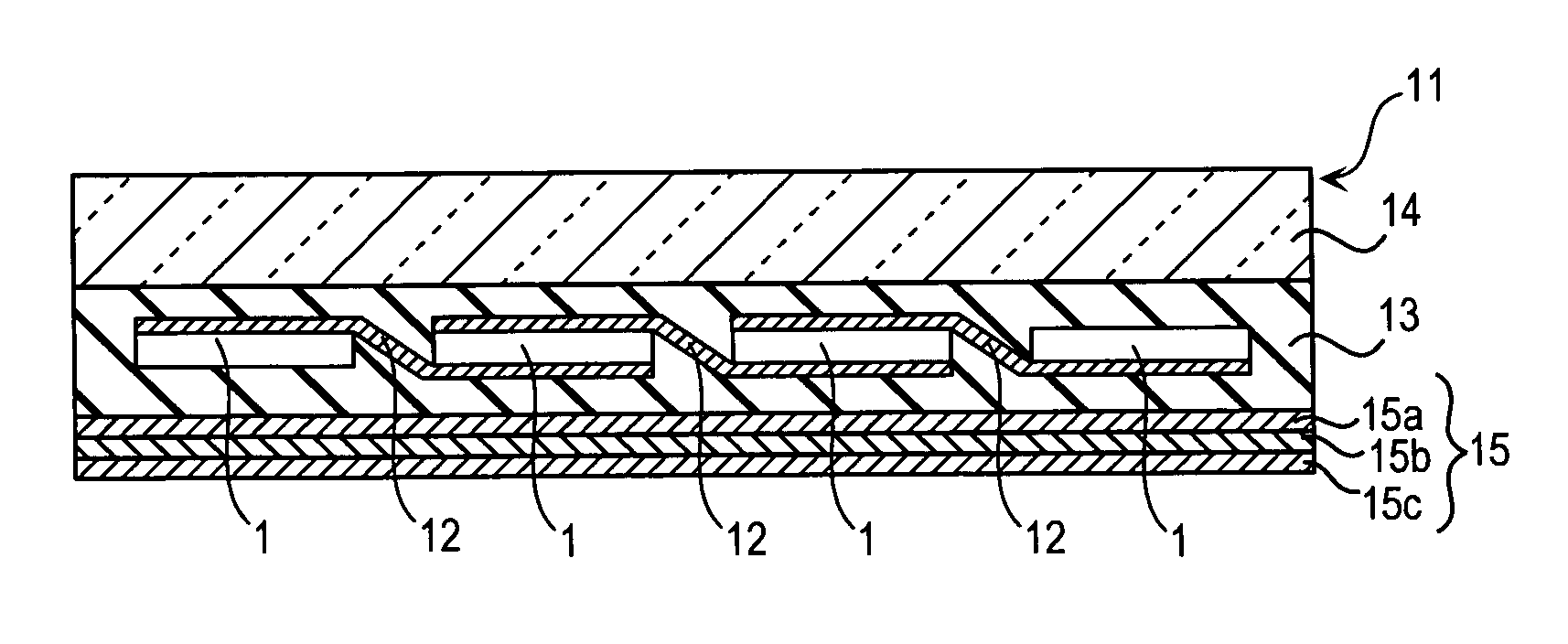
of Second Solar Cell Module

[0117] In this embodiment 1, solar cell modules were prepared with variation in compound ratio of epoxy resin, which was a material forming collector electrodes, for Examples 1-1 to 1-5 and Comparative examples 1-1 to 1-5. On each solar cell module, a temperature cycle test, a dump heat steady state test, and an evaluation test of insulation performance were conducted.

example 1-1

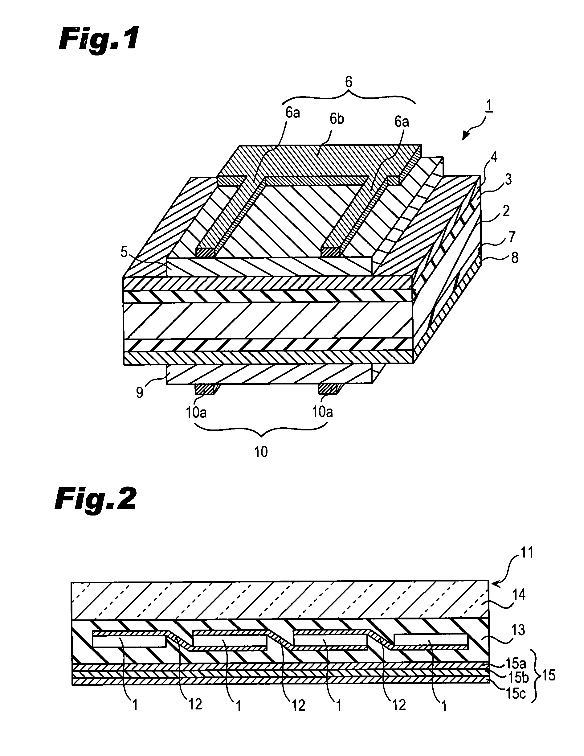
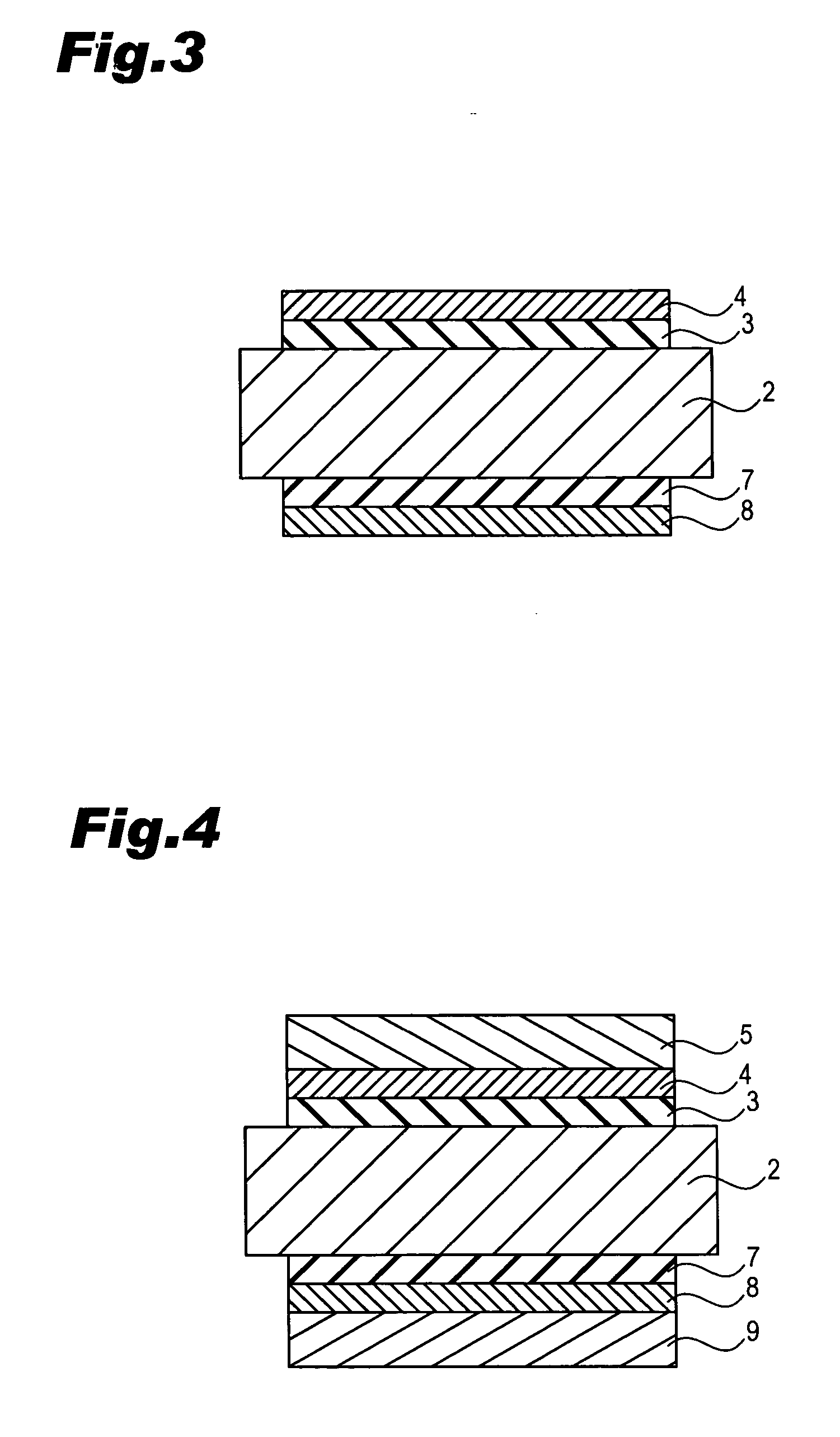
[0118] The solar cell element 1 is as same as that shown in FIGS. 1, 3 and 4. That is, as described above, a substantially intrinsic i-type amorphous silicon layer 3, a p-type amorphous silicon layer 4 are subsequently formed on an n-type single crystal silicon substrate 2.

[0119] In addition, an ITO film 5 is formed on the p-type amorphous silicon layer 4. A collector electrode (paste electrode) 6 is formed at a predetermined region on an upper surface of the ITO film 5. The collector electrode 6 is comprised of an electrically-conductive filler made of silver (Ag) and thermosetting resin. The thermosetting resin in the collector electrode 6 contains epoxy resin at ratio from 70% to 100% by volume. If the ratio of the epoxy resin in the resin binder is less than 100%, other resin component in the resin binder is all urethane resin.

[0120] On a lower surface of the n-type single crystal silicon substrate 2 formed are an i-type amorphous silicon layer 7 and an n-type amorphous silico...

example 1-2

[0152] In Example 1-2, resin material containing 70 vol. % bisphenol-A epoxy resin and 30 vol. % urethane resin is used for the conductive paste (silver paste) to form the collector electrodes 6 and 10. Except for this, the solar cell module of Example 1-2 is fabricated as in Example 1-1.


PUM


Abstract

A solar cell module of the present invention was made to improve adhesion between electrodes, which is formed with thermosetting resin containing silver paste, of a solar cell element and connecting tabs coated with lead (Pb) free solder. To achieve this purpose, the solar cell module is comprised of a front surface member, a rear surface protective member, a plurality of solar cell elements provided between the front surface member and the rear surface protective member, and connecting tabs for electrically connecting the solar cell elements to each other through electrodes with the use of lead free solder. The electrodes of the solar cell elements are made of silver paste containing thermosetting resin and silver powder. The thermosetting resin contains epoxy resin at volume ratio of 70% or more having a glass transition rate of 80° C. to 200° C. measured by a TMA method. The connecting tabs coated with lead free solder are soldered to the electrodes.

Description

BACKGROUND OF THE INVENTION [0001] 1. Field of the Invention [0002] The priority applications Number 2004-021387 and 2004-085185 upon which this patent application is based are hereby incorporated by reference. [0003] The present invention relates to a solar cell module, and more particularly, to a technique to improve the yield of a solar cell module. [0004] 2. Description of the Related Art [0005] Solar cells are being expected to be a new energy source that can convert light from the sun, which is a clean inexhaustible energy source, directly into electricity. [0006] Because a single solar cell outputs as small as a few watts, generally a plurality of solar cells are electrically connected in series or parallel to enhance the output to a few hundreds watts and used as a solar cell module to power houses and buildings. [0007]FIG. 19 is a cross-sectional view partially showing the structure of a conventional solar cell module. As shown in FIG. 19, a plurality of solar cell elements...

Claims


Application Information

Patent Timeline
Patent Type & Authority Applications(United States)
IPC IPC(8): H01L31/0224
CPCH01L31/022425H01L31/048H01L31/0504Y02E10/50H01L31/0747
Inventor YOSHIMINE, YUKIHIRONINOMIYA, KUNIMOTO
Owner PANASONIC INTELLECTUAL PROPERTY MANAGEMENT CO LTD
Why Eureka
Try Eureka