Converter

a converter and converter technology, applied in the field of converters, can solve the problems of unsolved problems mentioned below, large energy loss, and large energy loss of the conventional dc-dc converter, and achieve the effect of increasing the cost and size of the converter and large energy loss

Inactive Publication Date: 2005-09-15
SANKEN ELECTRIC CO LTD
View PDF3 Cites 30 Cited by
  • Summary
  • Abstract
  • Description
  • Claims
  • Application Information

AI Technical Summary

Benefits of technology

[0007] The conventional DC-DC converter, however, has unsolved problems mentioned below. For example, if the DC-DC converter develops an overheat or overvoltage state and the control circuit 4 is latched (storing data in a flip-flop FF41) to stop operation, the control circuit 4 provides no drive signal to the switching element Q1. Then, the tertiary winding C of the transformer T generat...

Problems solved by technology

The conventional DC-DC converter, however, has unsolved problems mentioned below.
In this case, the start-up circuit 5 continuously operates to cause a large energy loss.
This increases the cost and size of the converter.
Th...

Method used


Image

  • Converter
  • Converter
  • Converter

Examples


first embodiment

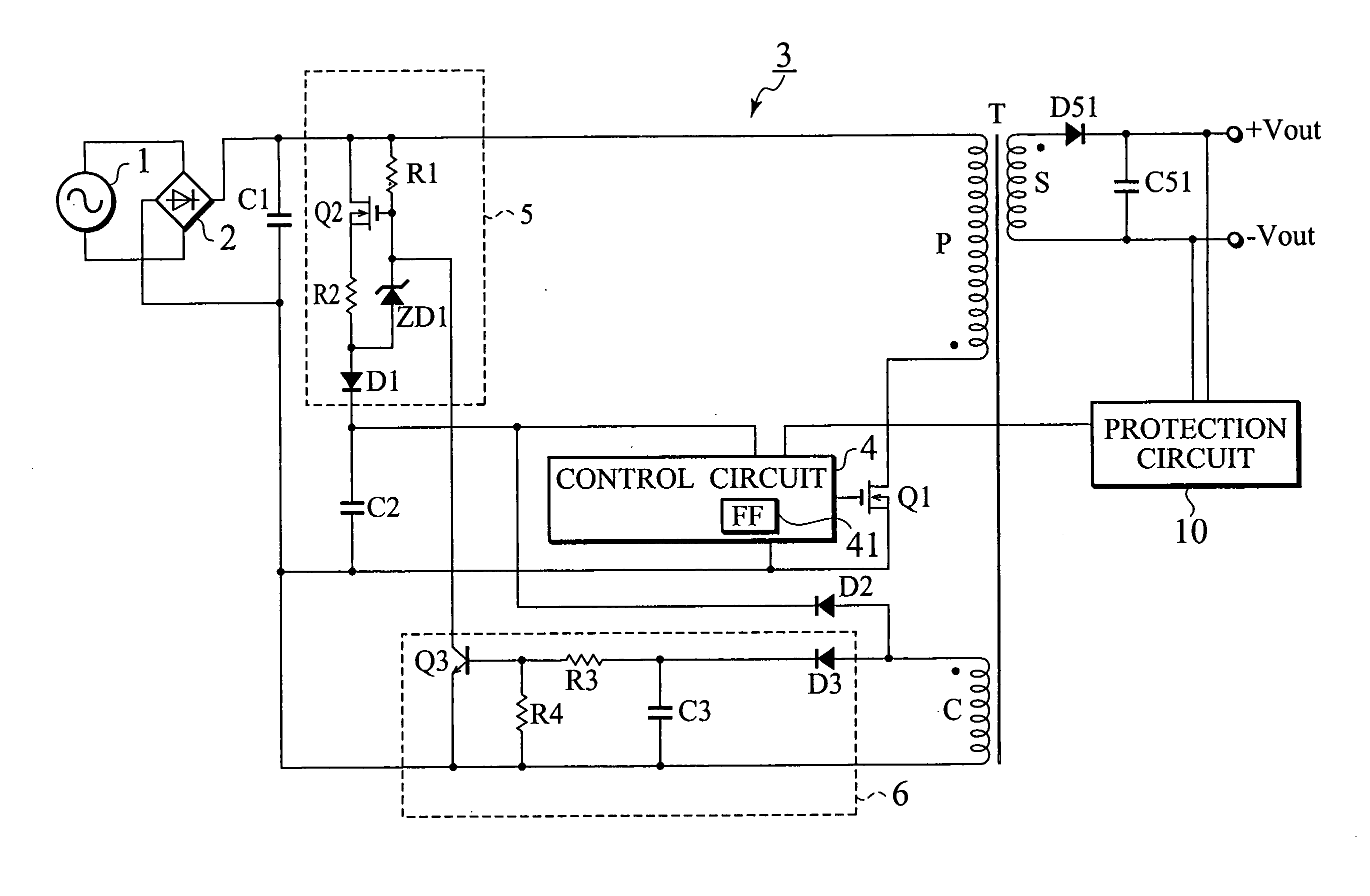
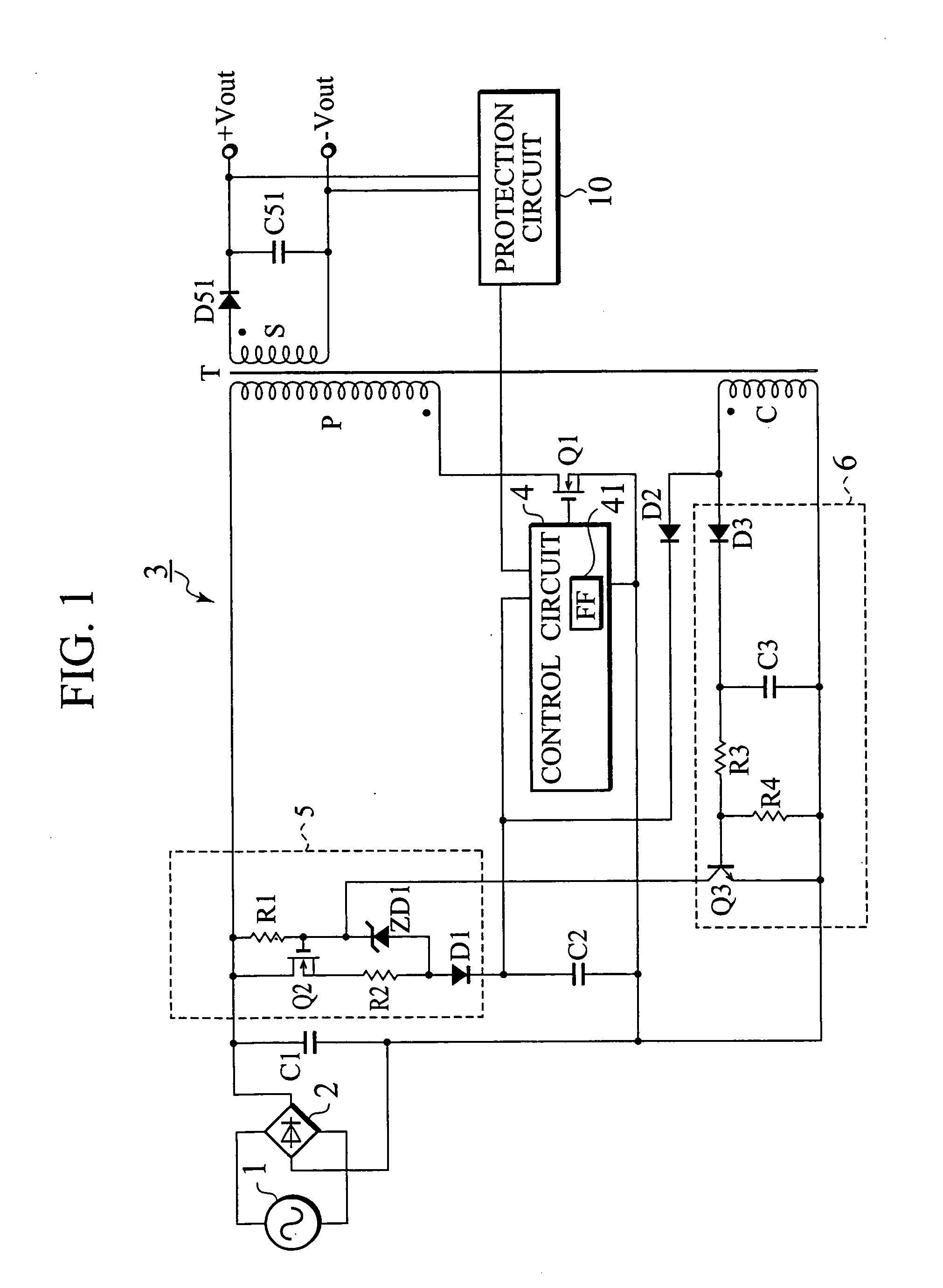
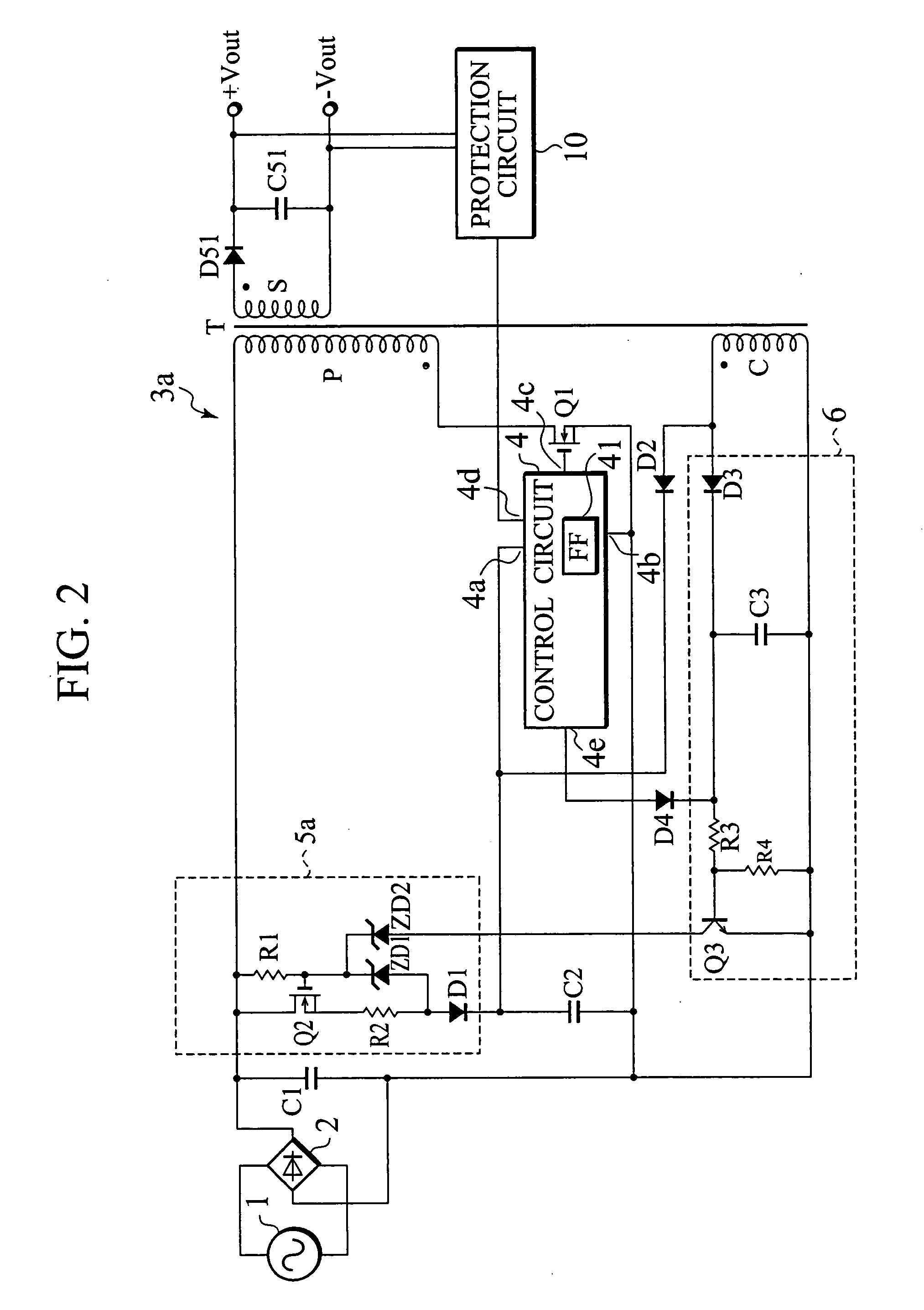
[0036]FIG. 2 is a view showing an arrangement of a DC-DC converter according to the first embodiment of the present invention. The DC-DC converter of FIG. 2 is different from the conventional DC-DC converter of FIG. 1 in that it additionally has a Zener diode ZD2 and a diode D4. In the DC-DC converter of FIG. 2, the same parts as those of the conventional converter of FIG. 1 are represented with the same reference marks.

[0037] In FIG. 2, a sinusoidal wave voltage from an AC power source 1 is rectified and smoothed by a full-wave rectifying circuit 2 and a capacitor C1, to provide a DC voltage. The DC voltage is supplied to the DC-DC converter 3a, which converts the input DC voltage into another DC voltage that is output from output terminals +Vout and −Vout.

[0038] The arrangement of the DC-DC converter 3a will be explained in detail. The capacitor C1 is connected through a primary winding P of a transformer T to a switching element Q1 made of a MOSFET. The switching element Q1 is ...

second embodiment

[0059]FIG. 4 is a view showing an arrangement of a converter according to the second embodiment of the present invention consisting of a power-factor improving converter and a DC-DC converter. In the converter of the second embodiment, the power-factor converter 7 has a choke coil L1, a switching element Q4, a diode D7, a power-factor improving control circuit (PFC control circuit) 71, and a capacitor C1 and is arranged in front of the DC-DC converter 3a.

[0060] The DC-DC converter 3a has already been explained in the first embodiment of FIG. 2, and therefore, will not be explained here. Only the power-factor improving converter 7 will be explained. The details of the arrangement of the power-factor improving converter 7 will be explained later.

[0061] In FIG. 4, the choke coil L1, switching element Q4, diode D7, power-factor improving control circuit (PFC control circuit) 71, and capacitor C1 form a step-up chopper circuit. The step-up chopper circuit steps up an input voltage from...

third embodiment

[0064]FIG. 5 is a view showing a DC-DC converter according to the third embodiment of the present invention. In the DC-DC converter of the first embodiment, a bias voltage to the gate of the switching element Q2 of the start-up circuit 5a is supplied from the capacitor C1. Unlike this, in the DC-DC converter of the third embodiment, a bias voltage to a gate of a switching element Q2 of a start-up circuit 5b is supplied from an AC power source 1 through diodes D5 and D6 and a resistor R1.

[0065] In the start-up circuit 5b, a first end of the AC power source 1 is connected to an anode of the diode D5. A cathode of the diode D5 is connected through the resistor R1 to the gate of the switching element Q2. A second end of the AC power source 1 is connected to an anode of the diode D6. A cathode of the diode D6 is connected through the resistor R1 to the gate of the switching element Q2. The other parts of the DC-DC converter of FIG. 5 are the same as those of the DC-DC converter of FIG. ...


PUM


Abstract

A converter is provided in which the cost and size of which are reduced by a decrease in current consumption with no need of large elements or radiation fins. The converter has a switching element (Q1) being connected to a DC power source through a primary winding (P) of a transformer (T), a control circuit (4) for turning on/off the switching element (Q1), a diode (D51) and a capacitor (C51) for rectifying/smoothing the voltage induced in the secondary winding (S) of the transformer (T) to extract DC output, and a starting circuit (5) for starting the control circuit (4). The starting circuit (5) operates as a constant current circuit (Q2, R1, R2, ZD1, D1) while starting the control circuit (4), and as a constant voltage circuit (Q2, R1, R2, ZD2, D1) after starting the control circuits (4).

Description

TECHNICAL FIELD [0001] The present invention relates to a converter, and particularly, to a start-up circuit provided for a DC-DC converter. BACKGROUND TECHNOLOGY [0002]FIG. 1 shows an example of a conventional DC-DC converter of that type. In FIG. 1, a sinusoidal wave voltage from an AC power source 1 is rectified and smoothed by a full-wave rectifying circuit 2 and a capacitor C1, to produce a DC voltage. The produced DC voltage is passed through a switching element Q1 and is applied to a primary winding P of a transformer T. The switching element Q1 is ON / OFF-controlled according to a drive signal from a control circuit 4. Although not shown, the control circuit 4 can control various circuits such as an output voltage feedback circuit, an output current feedback circuit, an output overvoltage protection circuit, an output voltage decrease detection circuit, and an overheat protection circuit. [0003] The DC voltage generated by the capacitor C1 turns on a constant-current start-up...

Claims


Application Information

Patent Timeline
IPC IPC(8): H02M1/00H02M1/36H02M3/335
CPCH02M3/33507H02M1/36
Inventor USUI, HIROSHIFUKUMOTO, YUKINARIRIKIISHI, YASUHIROOSAKA, SYOUHEI
Owner SANKEN ELECTRIC CO LTD
Why Eureka
Try Eureka