Laser source comprising amplifier and adaptive wavefront/polarization driver

a laser source and amplifier technology, applied in the direction of optical radiation measurement, instruments, manufacturing tools, etc., can solve the problems of unproven, unacceptable output beams, and complex control systems, and achieve the effect of a large degree yet unproven

Active Publication Date: 2005-09-15
NORTHROP GRUMMAN SYST CORP
View PDF4 Cites 120 Cited by
  • Summary
  • Abstract
  • Description
  • Claims
  • Application Information

AI Technical Summary

Benefits of technology

[0008] In a disclosed embodiment of the invention, the sensed phase and polarization differences result from a comparison between the phase and polarization of a reference signal and the phase and polarization properties sampled in the cross section of the solid state laser output signal. Thus, the step of predistorting the phase and polarization has the effect of compensating of phase and polarization distortions arising in the solid state laser.
[0009] Alternatively, or in addition, the step of predistorting the phase has the effect of achieving a desired change in wavefront tilt or focus of the solid state laser output beam. Thus the output beam may be steered to a limited extent, or focused as desired in a particular application.

Problems solved by technology

The bulk crystal approaches suffer from thermo-optical distortions of the laser medium that render the output beams unacceptable, though fabrication of high power SSL devices has been demonstrated.
Fiber array approaches, on the other hand, promise exquisite control of the output wavefront, but require control systems that are complex and to a large degree yet unproven.

Method used


Image

  • Laser source comprising amplifier and adaptive wavefront/polarization driver
  • Laser source comprising amplifier and adaptive wavefront/polarization driver
  • Laser source comprising amplifier and adaptive wavefront/polarization driver

Examples


Embodiment Construction

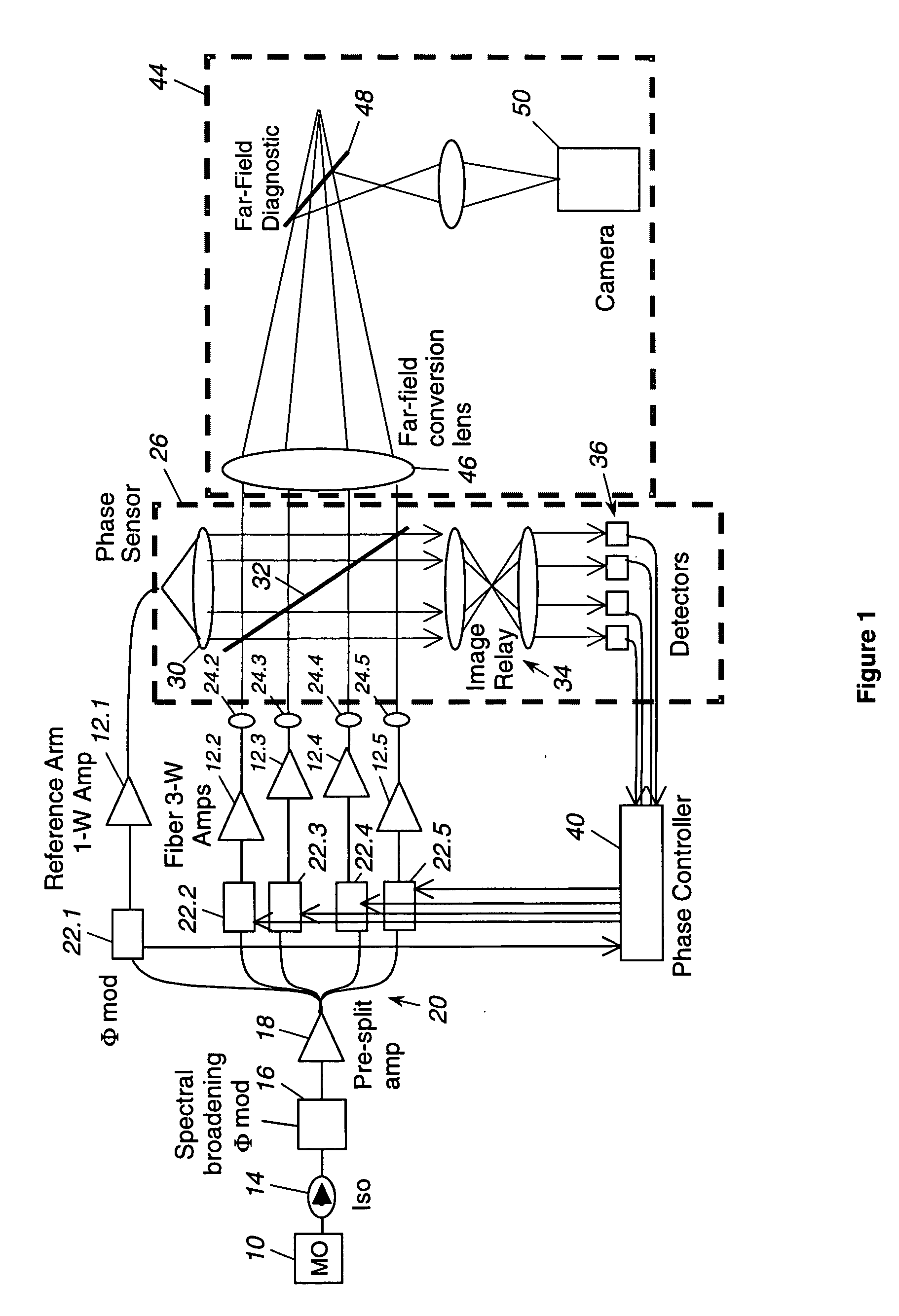
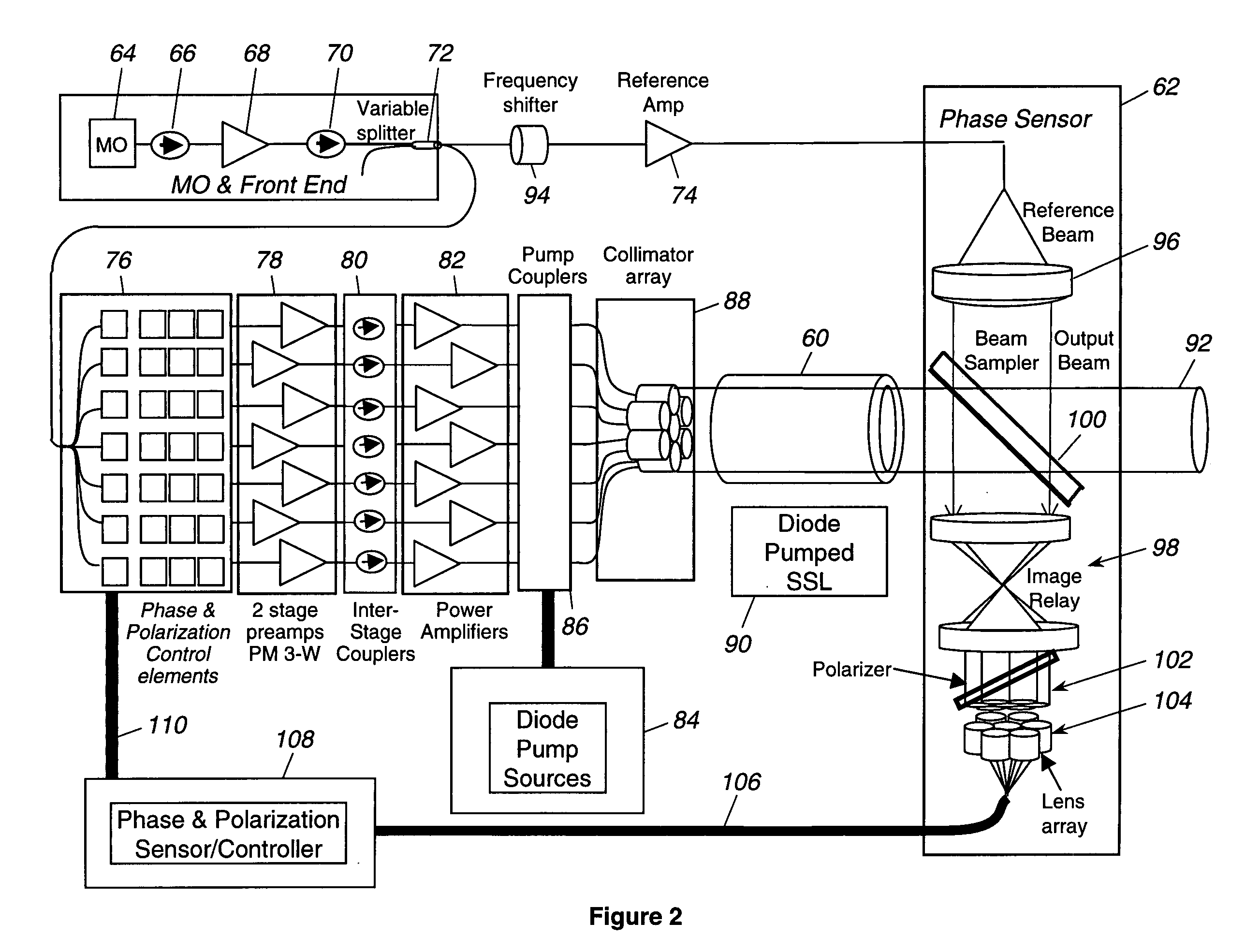
[0013] As shown in the drawings for purposes of illustration, the present invention is concerned with laser sources scalable to high powers, for any of a variety of applications in both military and industrial fields. FIG. 1 shows a scalable fiber laser architecture in which a master oscillator (MO), indicated by reference numeral 10, defines the spectrum and modulation waveform of light that is distributed to an array of high power fiber amplifiers, of which five are shown, as indicated by numerals 12.1-12.5. Associated with the master oscillator 10 are an optical isolator 14, a spectral broadening phase modulator 16 and a pre-split amplifier 18. The output of the pre-split amplifier 18 is divided into multiple optical paths, as indicated diagrammatically at 20, and each path passes through a phase modulator, indicated by 22.1-22.5. The fiber amplifiers 12 are pumped by laser diode arrays (not shown) and the output beams from the fiber amplifiers are combined in a closely packed le...


PUM

PropertyMeasurementUnit
poweraaaaaaaaaa
phaseaaaaaaaaaa
heat capacityaaaaaaaaaa

Abstract

A hybrid laser source including a solid state laser driven by an array of fiber laser amplifiers, the inputs of which are controllable in phase and polarization, to compensate for distortions that arise in the solid state laser, or to achieve desired output beam properties relating to direction or focus. The output beam is sampled and compared with a reference beam to obtain phase and polarization difference signals across the output beam cross section, at spatial positions corresponding with the positions of the fiber laser amplifiers providing input to the solid state laser. Therefore, phase and polarization properties of the output beam may be independently controlled by predistortion of these properties in the fiber laser amplifier inputs.

Description

BACKGROUND OF THE INVENTION [0001] This invention relates generally to high power laser sources and, more particularly, to solid state lasers or fiber phased array lasers that are scalable to high powers. There is a significant need for high power laser sources for both military and industrial applications, such as directed energy weapons (DEW) systems, ladar and illuminators, as well as industrial cutting, welding and material processing. Scalable laser technologies under development fall into two principal categories: bulk crystal solid state lasers (SSL) and fiber phased array sources. In the bulk crystal group, slab lasers, rod lasers, disk lasers and heat capacity lasers are all under active consideration. In the fiber laser area, there are approaches that feature active near field beam control, far field beam control, passive beam combining using pulse code modulation (PCM) technology and nonlinear beam combining. The bulk crystal approaches suffer from thermo-optical distorti...

Claims


Application Information

Patent Timeline
Patent Type & Authority Applications(United States)
IPC IPC(8): B23K26/06B23K26/42G01J9/02H01S3/00H01S3/06H01S3/067H01S3/094H01S3/0941H01S3/10H01S3/13H01S3/131H01S3/23
CPCB23K26/0604H01S3/1301B23K26/426G01J9/02H01S3/0014H01S3/005H01S3/0064H01S3/0604H01S3/06758H01S3/094003H01S3/094038H01S3/0941H01S3/10007H01S3/10015H01S3/10053H01S3/10092H01S3/1304H01S3/1305H01S3/2383B23K26/0608B23K26/705H01S3/1307H01S3/2375
Inventor RICE, ROBERT R.WICKHAM, MICHAEL G.KOMINE, HIROSHI
Owner NORTHROP GRUMMAN SYST CORP
Why Eureka
Try Eureka