Method and device for manufacturing bare optical fiber

Inactive Publication Date: 2005-09-15
NTT ELECTORNICS CORP +1
View PDF2 Cites 12 Cited by
  • Summary
  • Abstract
  • Description
  • Claims
  • Application Information

AI Technical Summary

Benefits of technology

[0009] To achieve the above-described object, according to a first aspect of the invention, there is provided a method for manufacturing a bared optical fiber in which a laser beam is applied to a coated optical fiber: to fuse a coating if a coating material has a lower melting point as compared with a material of the bared optical fiber; to fuse and volatilize the coating if the coating material has a lower volatilizing point as compared with the material of the bared optical fiber; to sublimate the coating if the coating

Problems solved by technology

Still further, in order to reduce the size of an optical fiber coupler, the selective removal of only a portion to be fused of the coating from the coated optical fiber has become an critical problem.
However, in either of these two cases, when the coating is completely cut, these tools might damage even a bared optical fiber.
This makes the end surface of the remaining coating uneven.
Further, since the metallic blades are put on the coated optical fiber, in a case where the metallic blades cause damage to the surface of the bared optical fiber, the damage becomes causes of the occurrence of cracks or a

Method used


Image

  • Method and device for manufacturing bare optical fiber
  • Method and device for manufacturing bare optical fiber
  • Method and device for manufacturing bare optical fiber

Examples


embodiment 1

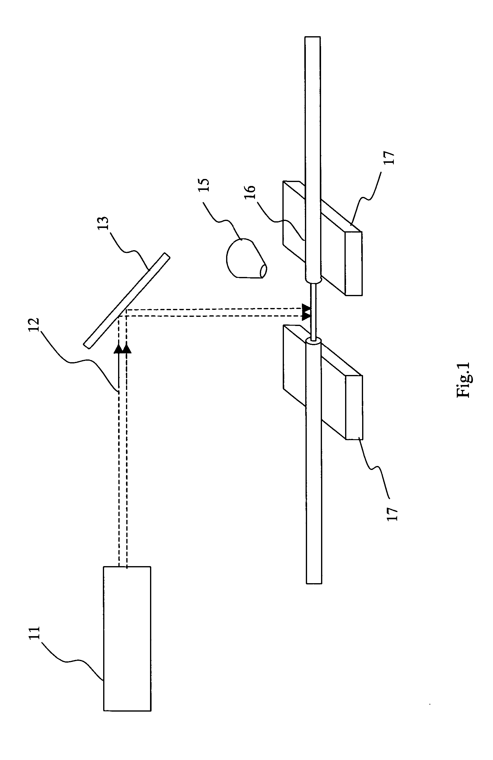
[0031] An embodiment of removing the coating of a coated single optical fiber is shown in FIG. 1. A reference numeral 11 denotes a LASER for emitting a laser beam 12, 13 denotes a mirror for reflecting the laser beam, 15 denotes a gas nozzle for blowing inert gas over a portion of the coated optical fiber to which the laser beam 12 is applied, 16 denotes a coated single optical fiber whose coating is to be removed, and 17 denotes a stage for moving the coated single optical fiber 16 in the axial direction of the coated optical fiber.

[0032] The stage 17, although not shown, is provided with a clamping part for griping the optical fiber. All that this clamping part needs to do is to fix the optical fiber to prevent the optical fiber from moving and the clamping part does not need to apply a heavy pressing force to the optical fiber, dislike a conventional wire stripper. Hence, the clamping part can have a simple structure and its portion that presses the optical fiber can be made sho...

embodiment 2

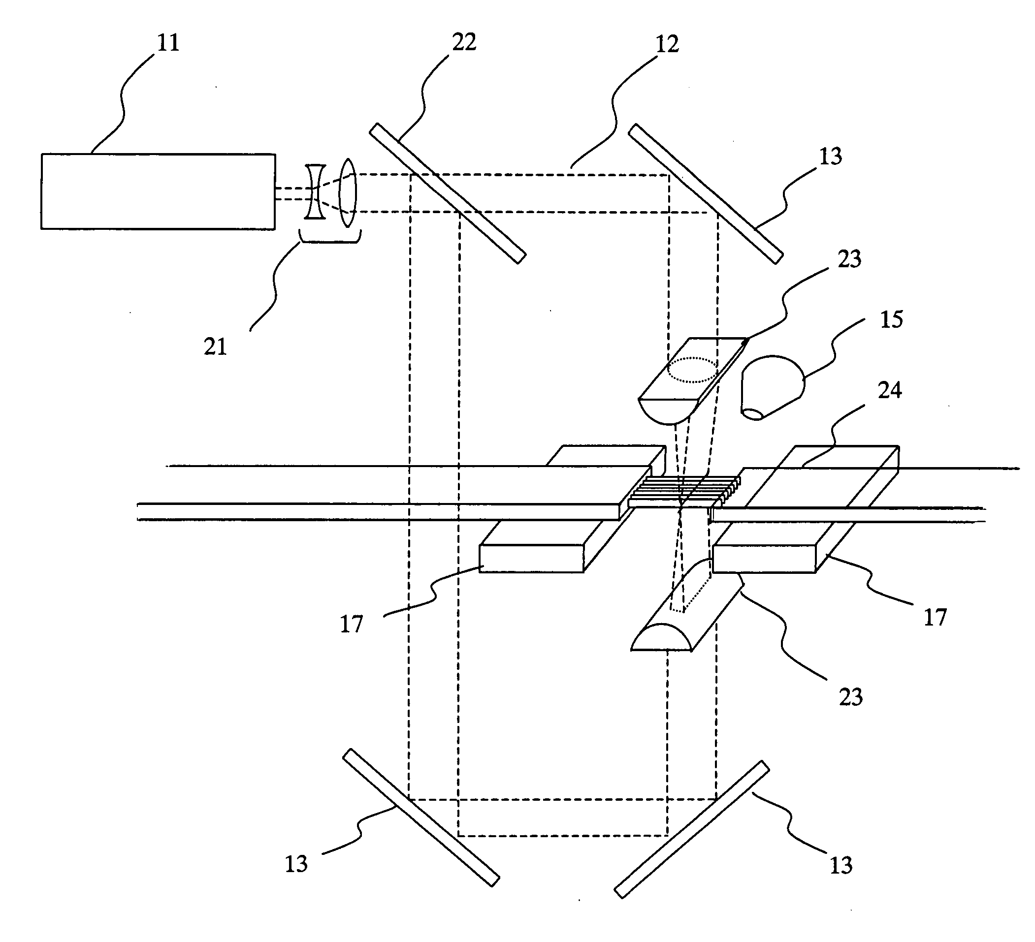
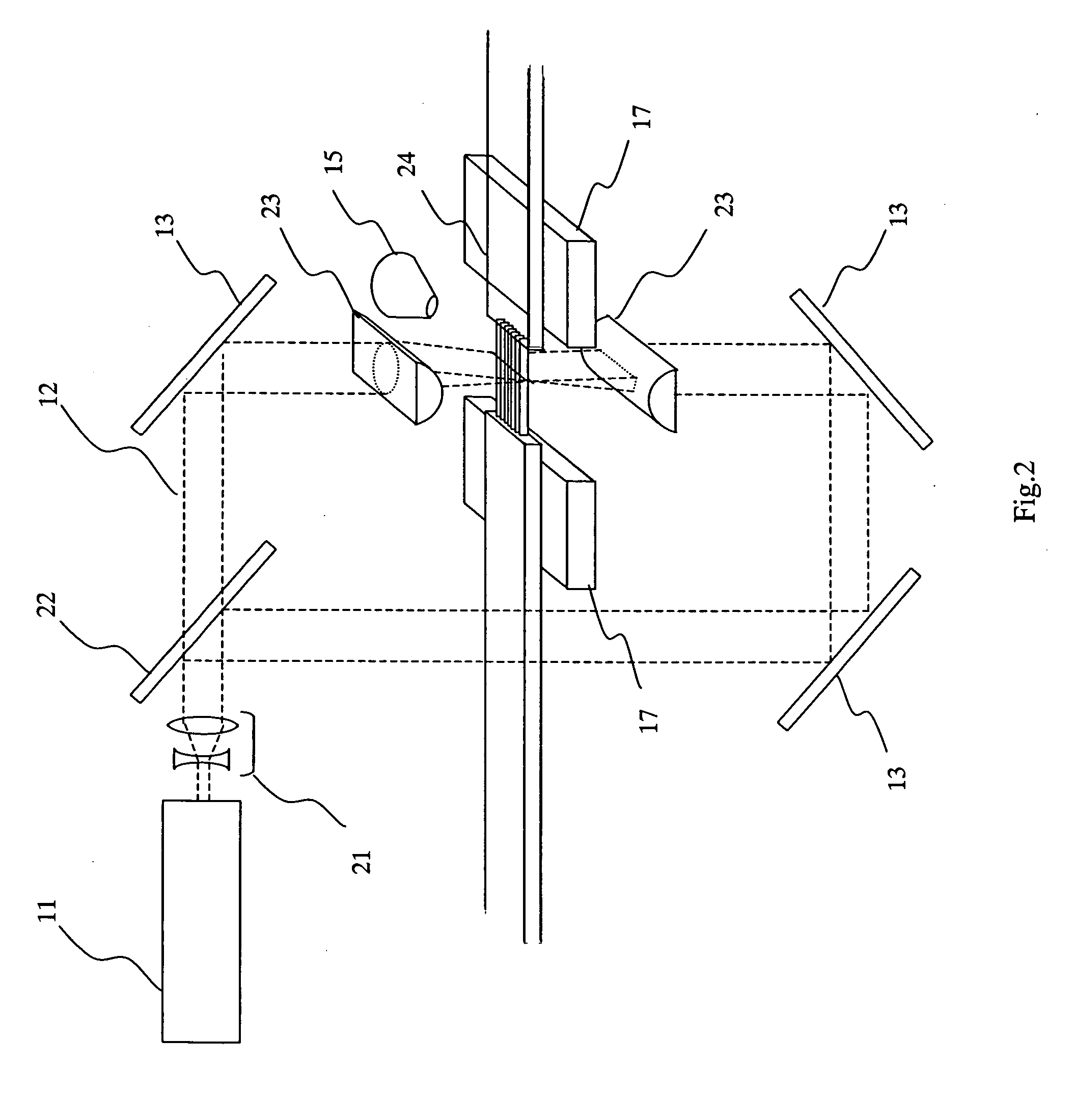
[0040] An embodiment of removing the coating of the coated optical multi fiber is shown in FIG. 2. A reference numeral 11 denotes a LASER for emitting a laser beam 12, 21 denotes a beam expander for expanding the laser beam, 22 denotes a half mirror, 13 denotes a mirror for reflecting the laser beam, 23 denotes a cylindrical lens for focusing a circular laser beam into the shape of a belt, 15 denotes a gas nozzle for blowing inert gas over a portion of the coated optical fiber to which the laser beam 12 is applied, 24 denotes a coated optical multi fiber having bared optical fibers integrally formed in the shape of a tape by means of a coating material, and 17 denotes a stage for moving the optical multi fiber 24 in an axial direction of the coated optical multi fiber.

[0041] The stage 17, although not shown, is provided with a clamping part for griping the coated optical fiber. All that this clamping part needs to do is to fix the coated optical fiber to prevent the coated optical ...

embodiment 3

[0052] An embodiment of removing the coating of the coated optical multi fiber is shown in FIG. 5. In Embodiment 2, the laser beam is guided by use of a spatial beam, but in FIG. 5, an optical system using a hollow fiber coated with silver is used. In FIG. 5, a reference numeral 11 denotes a LASER emitting a laser beam 12, 22 denotes a half mirror, 13 denotes a mirror reflecting the laser beam, 31 denotes a hollow fiber for guiding the laser beam, 23 denotes a cylindrical lens for focusing a circular laser beam into the shape of a belt, 15 denotes a gas nozzle for blowing inert gas over a portion of the optical fiber to which the laser beam 12 is applied, 24 denotes a coated optical multi fiber having bared optical fibers integrally formed in the shape of a tape by means of the coating material, and 17 denotes a stage moving the coated optical multi fiber 24 in the axial direction of the coated optical fiber.

[0053] In this embodiment, the laser beam of high energy is not propagated...


PUM


Abstract

An object of the present invention is to provide a method for manufacturing a bared optical fiber having a good end surface of a coating when the coating of the coated optical fiber is removed, and a device for manufacturing the same. To achieve the above object, according to the invention, a laser beam is applied to an coated optical to fuse the coating or work the coating in other manners, if a coating material has a lower melting point as compared with the material of the bared optical fiber to remove the coating, whereby a bared optical fiber is manufactured. In addition, a cyanogen gas generated when the coating of the coated optical fiber is fused or worked in other manners is decomposed by ozone, thereby being made harmless.

Description

TECHNICAL FIELD [0001] The present invention relates to a method for manufacturing a bared optical fiber by well removing the coating from a coated optical fiber, and a device for manufacturing the same. BACKGROUND ART [0002] With the increasing introduction of an optical communication system, a coating for protecting an bared optical fiber needs to be removed with high precision when bared optical fibers are fused and spliced to each other and when an bared optical fiber is worked into an optical connector. Further, the technological development of wavelength division multiplexing transmission has advanced to cope with a request for increasing communication capacity and the coating of a coated optical multi fiber has been required to be efficiently removed when the coated optical multi fiber is connected to an arrayed waveguide type wavelength division multiplexer / demultiplexer which applies to wavelength division multiplexing transmission. Still further, in order to reduce the siz...

Claims


Application Information

Patent Timeline
IPC IPC(8): G02B6/245
CPCG02B6/245
Inventor ARISHIMA, KOICHIKUROSAWA, YOSHIKOBAYASHI, MASARUHIRAYAMA, MAMORUNAGASE, RYO
Owner NTT ELECTORNICS CORP
Why Eureka
Try Eureka