Heat treatment method and heat treament apparatus

a heat treatment method and heat treatment apparatus technology, applied in the direction of laboratory glassware, semiconductor/solid-state device testing/measurement, instruments, etc., can solve the problems of poor uniform thickness of oxide films formed on production wafers between surfaces (between wafers), high cost burden, and strong film thickness of wafers located at a portion on the downstream side. , to achieve the effect of improving the uniform thickness of thin films and less operator burden

Active Publication Date: 2005-09-15
TOKYO ELECTRON LTD
View PDF5 Cites 26 Cited by
  • Summary
  • Abstract
  • Description
  • Claims
  • Application Information

AI Technical Summary

Benefits of technology

[0016] This invention is intended to solve the above problems. The object of this invention is to provide a technique that can improve uniformity of film thickness of thin films between surfaces when the thin films are formed on the surfaces of respective substrates by conducting a thermal process to a plurality of substrates at one time. In addition, another object of this invention is to provide a technique that can obtain the same process result independent on the number of productions to be thermally processed, with less operator's burden.
[0032] According to the invention, since the temperature set values for the thermal process are set by using the first substrates and then corrected by using the second substrates, wherein the first substrates need less consumption of the process gas than the production substrates and the second substrates need more consumption of the process gas than the first substrates, even if there is some loading effect (phenomenon in which thickness of thin films formed on substrates located on a downstream side of the process gas is thinner, because substrates located on an upstream side thereof consume the process gas), the difference with the target thickness that may be caused by the loading effect may be canceled by the correction of the temperature set values. Thus, in the thermal process using the corrected temperature set values, high uniformity of film thickness of the thin films on production substrates may be obtained between the zones.
[0037] In the third thermal processing step, production substrates may be fully arranged in the holding region for substrates to be processed in the substrate holder. Alternatively, less number of production substrates may be arranged. In the latter case, it is preferable that the production substrates are arranged at a portion on an upstream side of a flow of the process gas introduced into the reaction container, in the holding region for substrates to be processed in the substrate holder, and the first substrates are arranged at the residual portion in the holding region. In the case, independent on the number of productions to be processed at one batch, the same thermal processing result can be obtained. In addition, as the temperature set values for the respective zones in the reaction container are common, operator's burden may be reduced and miss in setting temperatures may be prevented.

Problems solved by technology

Thus, if the production wafers are used, especially if the production wafers have larger diameters, burden of cost is great, which is not preferable.
However, in the above oxidation process using the radicals, even if the adjusting operation of the temperature set values is conducted by using dummy wafers, uniformity of thickness of oxide films formed on production wafers between surfaces (between wafers) is bad.
However, when the trench wafers were used, the tendency that film thickness of wafers located at a portion on a downstream side is thin is strong.
Thus, the oxidation process using the radicals may suffer from the loading effect in the conventional manner, so that it is difficult to secure high uniformity of film quality of the oxide films between surfaces.
In addition, if process condition such as a temperature is determined depending on the arrangement layout of the production wafers, the setting operation of the process condition is troublesome.
In addition, if process condition such as a temperature of each zone of the reaction container, a pressure, a gas flow rate and a processing time, is set depending on the number and / or the arrangement layout of production wafers arranged on the wafer boat, some operation miss is likely to occur.

Method used


Image

  • Heat treatment method and heat treament apparatus
  • Heat treatment method and heat treament apparatus
  • Heat treatment method and heat treament apparatus

Examples


example

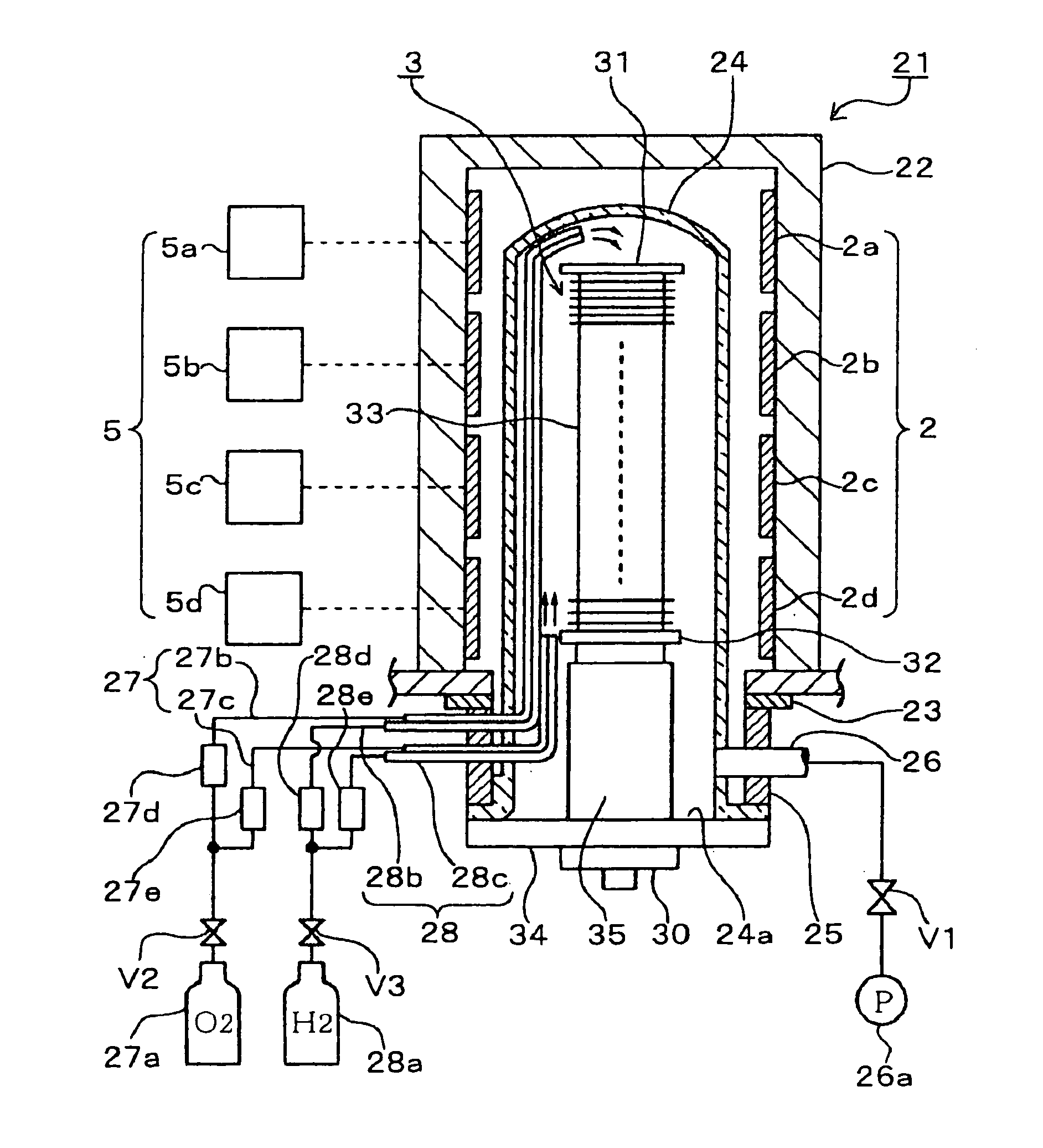
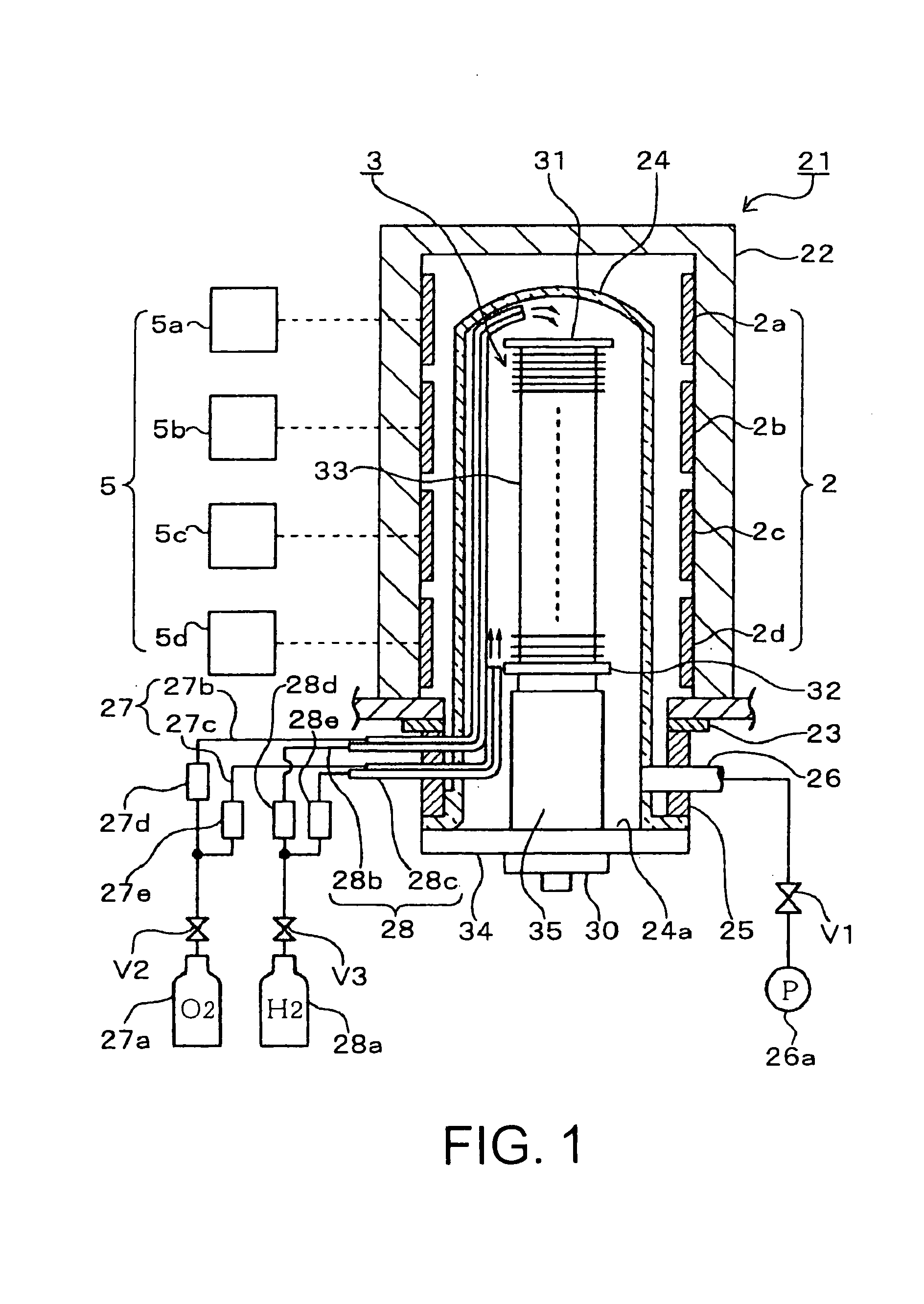
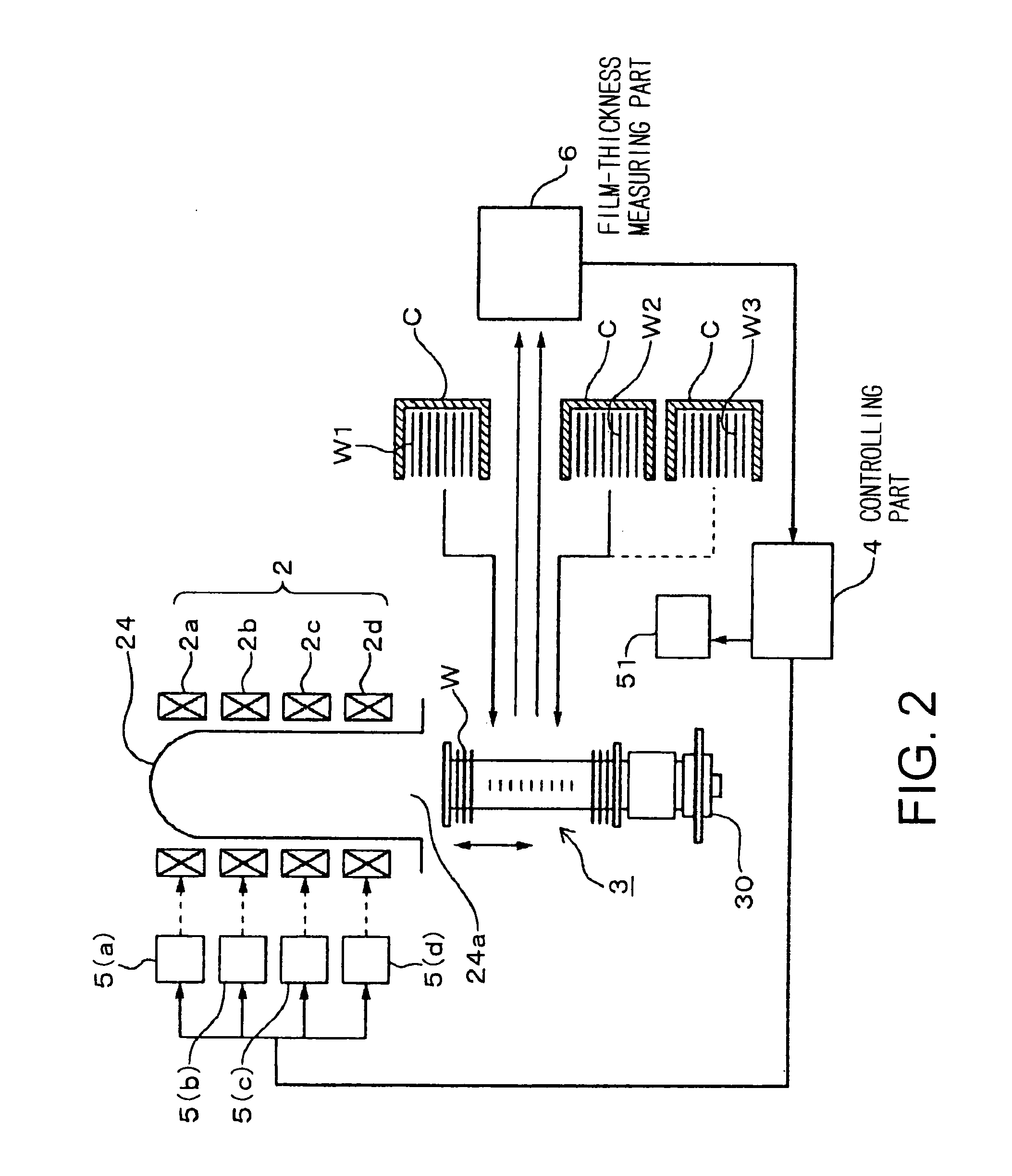
[0110] A wafer boat, which can hold 100 wafers in a holding area for production wafers, was used, dummy wafers were fully arranged in the holding area for production wafers, and an oxidation process as a thermal process was conducted. In an area other than the holding area for production wafers of the wafer boat, such as in an uppermost area and a lowermost area of the wafer boat, dummy wafers called side dummy wafers or the like were arranged. Regarding the thermal process condition, a temperature of the thermal-processing atmosphere was 1000° C., and flow rates of an O2 gas and an H2 gas were O2:H2=2:1. Herein, the temperature of the thermal-processing atmosphere means for example a set temperature at a central portion in a vertical direction of the holding area for the production wafers. Then, an adjusting operation of the temperature set values for the respective zones of the reaction container was conducted in such a manner that respective film thicknesses of monitor wafers loc...


PUM

PropertyMeasurementUnit
thicknessaaaaaaaaaa
temperatureaaaaaaaaaa
thicknessaaaaaaaaaa

Abstract

The present invention relates to a thermal processing method including thermal processing steps having: a step of holding a plurality of substrates by means of a substrate holder, a step of conveying the substrate holder into a reaction container, a step of heating a plurality of zones of thermal process atmosphere in the reaction container by means of a plurality of heating units, respectively, and a step of forming thin films on surfaces of the plurality of substrates by introducing a process gas into the reaction container. The thermal processing method includes: a first thermal processing step of carrying out the thermal processing steps by using a plurality of first substrates as the plurality of substrates, wherein thin films are formed on surfaces of the plurality of first substrates by means of less consumption of the process gas than on surfaces of production substrates; a first measuring step of measuring a thickness of the thin films formed on the surfaces of the plurality of first substrates for each of the plurality of zones of the thermal process atmosphere in the reaction container; and a first setting step of setting respective temperature set values of the plurality of heating units in such a manner that the thickness measured for each of the plurality of zones substantially coincides with a target thickness of thin films to be formed on the surfaces of production substrates, based on measurement result of the first measuring step. Then, a second thermal processing step of carrying out the thermal processing steps by using a plurality of second substrates as the plurality of substrates, wherein thin films are formed on surfaces of the plurality of second substrates by means of more consumption of the process gas than on the surfaces of the plurality of first substrates, and wherein the plurality of heating units are respectively adjusted to the respective temperature set values set by the first setting step; a second measuring step of measuring a thickness of the thin films formed on the surfaces of the plurality of second substrates for each of the plurality of zones of the thermal process atmosphere in the reaction container; and a second correcting step of correcting the respective temperature set values of the plurality of heating units in such a manner that the thickness measured for each of the plurality of zones substantially coincides with the target thickness of thin films to be formed on the surfaces of production substrates, based on measurement result of the second measuring step; are carried out. Then, a third thermal processing step of carrying out the thermal processing steps by using at least a plurality of production substrates as the plurality of substrates, wherein the plurality of heating units are respectively adjusted to the respective temperature set values corrected by the second correcting step, is carried out.

Description

TECHNICAL FIELD [0001] The present invention relates to a thermal processing method and a thermal processing unit of a batch type, wherein a thermal process is conducted to a large number of substrates such as semiconductor wafers at a time. BACKGROUND ART [0002] In manufacturing semiconductor devices, various thermal processes such as an oxidation process or a CVD process (chemical vapor deposition) are conducted to semiconductor wafers. As a thermal processing unit of a batch type that carries out such a thermal process, a longitudinal type of thermal processing unit is known. In the unit, a large number of wafers are held by a holder, which is called a wafer boat, in a tier-like manner, and the holder is conveyed into a longitudinal type of thermal processing furnace, for example thorough a lower part of the thermal processing furnace. Then, atmosphere in the thermal processing furnace is made to be heating atmosphere of a predetermined temperature, and a thermal process is condu...

Claims


Application Information

Patent Timeline
Patent Type & Authority Applications(United States)
IPC IPC(8): C23C16/46C23C16/52H01L21/31H01L21/00H01L21/316H01L21/66
CPCC23C16/46C23C16/52H01L21/0217H01L21/02211H01L21/02238H01L21/02255Y10T436/25H01L21/31662H01L21/67109H01L21/67248H01L21/67253H01L22/20H01L21/02271H01L21/324H01L21/205
Inventor SUZUKI, KEISUKEWANG, WENLINGYONEKAWA, TSUKASAIKEUCHI, TOSHIYUKISATO, TORU
Owner TOKYO ELECTRON LTD
Why Eureka
Try Eureka