
Cryogenic assembly

a technology of cryogenic assembly and assembly body, which is applied in the direction of superconducting magnets/coils, gas/liquid distribution and storage, lighting and heating apparatus, etc., can solve the problems of helium boil-off, service operation is considered problematic, and become resistive, so as to reduce the pressure difference in the neck, improve the contact between components and cooling fluids, and reduce the heat load on the effect of components

Active Publication Date: 2005-09-22
SIEMENS HEALTHCARE LTD +1
View PDF12 Cites 19 Cited by
  • Summary
  • Abstract
  • Description
  • Claims
  • Application Information

AI Technical Summary

Benefits of technology

The invention is a cryostat assembly that can hold electrical, electronic, or magnetic devices in a cryogenic fluid. It has a service neck with two current leads, one of which is formed by the neck tube wall. This design reduces pressure differences and improves cooling, while also providing separate paths for fluid release from the neck. This results in lower heat loads on the components and better contact with the cooling fluid.

Problems solved by technology

Any dissipation in the components or heat getting into the system causes helium boil-off.
This service operation is considered as problematic by many users and great efforts have been made over the years to introduce refrigerators that either reduce the rate of boil-off, or recondense any lost liquid back into the bath.
A suitable means must be available for the gas to exit from the cryostat, but it is one function of the cryostat to reduce this boiling to as low a value as practical since gases such as helium are expensive commodities.
The heat generated in this resistive section heats the adjacent parts of the magnet and causes them to become resistive.
There are several disadvantages of such an access neck configuration.
Secondly, there is no means of providing a controlled de-energization of the magnet except by fitting the removable current lead, which means that a trained service engineer is required.
Thirdly, the back pressure during a quench process is high because of the use of multiple radiation baffles.
Furthermore the heat load at the magnet connector is typically high during energization of the magnet, leading to high helium loss.
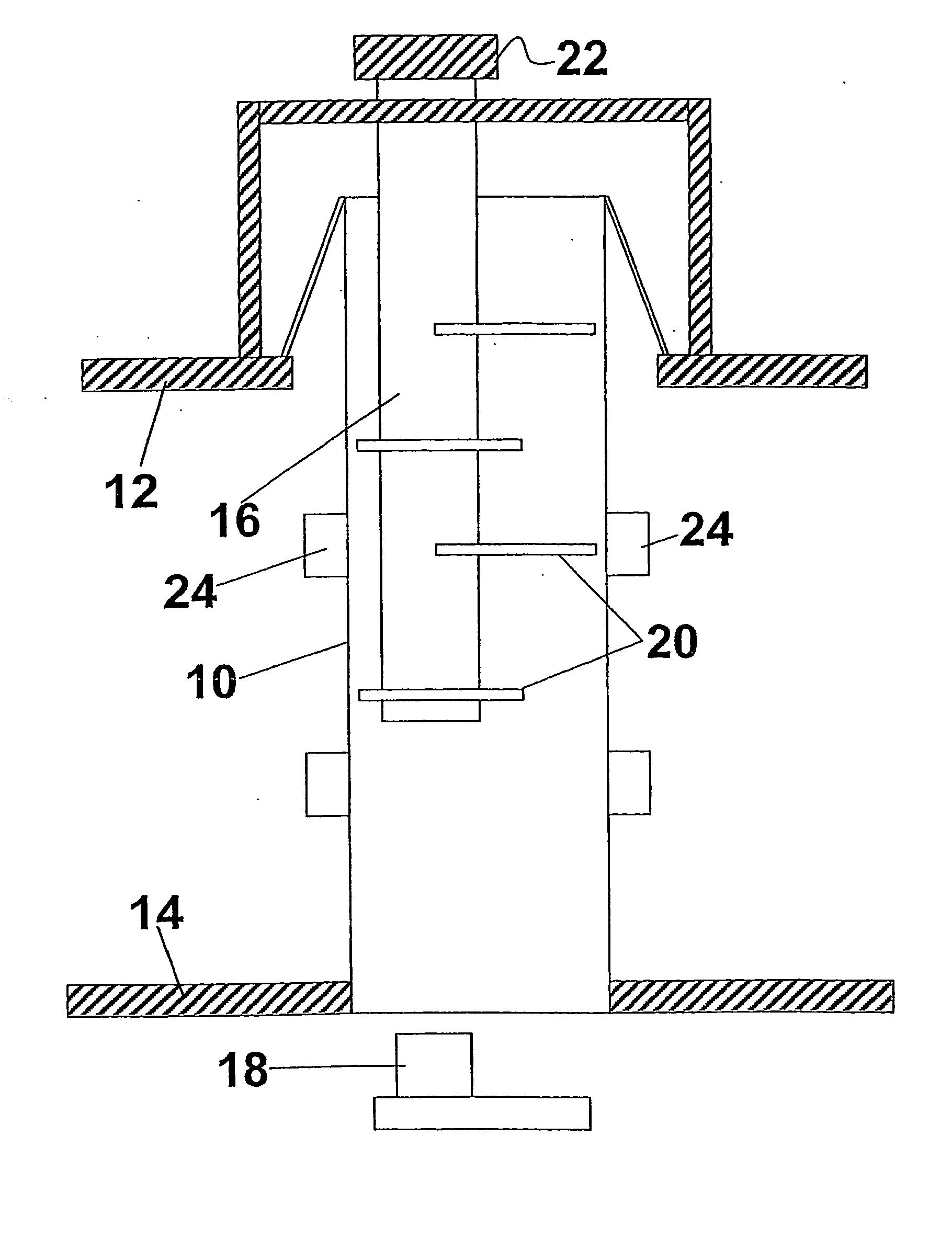
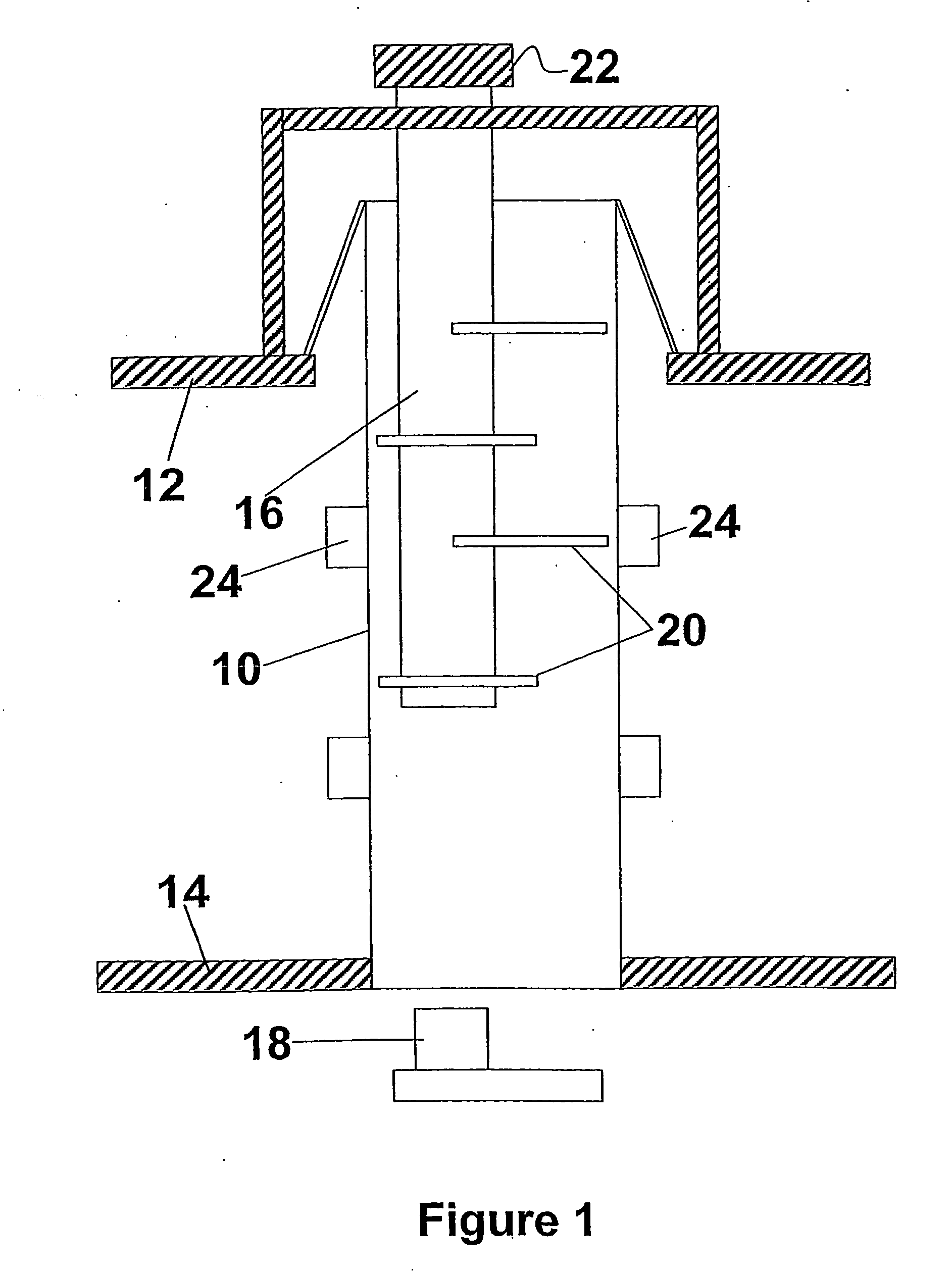
Additionally the thermal connections 24 connect only to the outside of the service neck tube 10 and as such are not ideal because of non-optimal thermal contact with the gas in the neck tube.
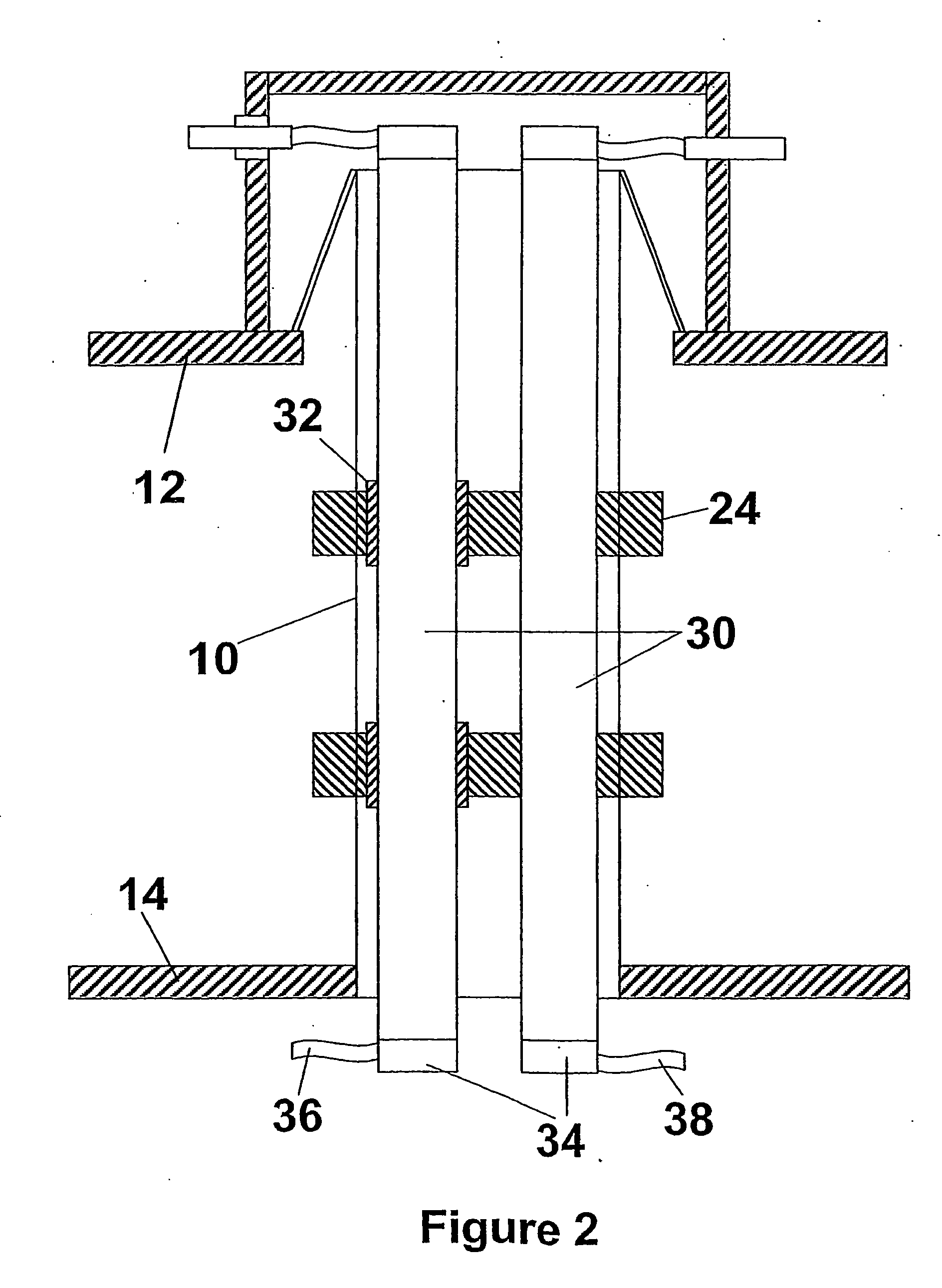
Some of the disadvantages of this access neck are that the back pressures developed during a quench process can be high; this is because the gas must be vented primarily up the fixed leads in order to ensure that they are adequately cooled during magnet energization.
The cooling of the gas column is not particularly efficient because the boil-off gas passes primarily up the two fixed leads.
The diameter of the leads cannot be made large because other service operations and fittings must also be provided through the neck and if the neck diameter is increased the heat load increases.
Balancing the three parallel gas streams in a neck assembly requires precise knowledge of the gas impedances which is hard to predict and even harder to control in taking manufacturing tolerances into account.

Method used


Image

  • Cryogenic assembly
  • Cryogenic assembly
  • Cryogenic assembly

Examples


Embodiment Construction

[0025] There will now be described, by way of example, the best mode contemplated by the inventors for carrying out the invention. In the following description, numerous specific details are set out in order to provide a complete understanding of the present invention. It will be apparent, however, to those skilled in the art, that the present invention may be put into practice with variations of this specific.

[0026]FIG. 3 shows a schematic representation of a cryostat for a whole body magnetic resonance imaging device which operates at superconducting temperatures. There is a liquid helium vessel 40 which encloses a superconducting magnet 44. A service neck 42 is provided to enable access to the magnet.

[0027] Referring now to FIG. 4, there is shown a first embodiment of the invention. Service neck 50 is provided between the outer walls 12 of a cryostat and the walls 14 of a helium vessel. Electrical cabling wires 56 and 58 connect with the terminals of a magnet (not shown). Two d...


PUM

PropertyMeasurementUnit
transition temperatureaaaaaaaaaa
temperatureaaaaaaaaaa

Abstract

The present invention relates to a cryostat having a service neck for access to a superconducting magnet. In many cryogenic applications components, e.g. superconducting coils for magnetic resonance imaging (MRI), superconducting transformers, generators, electronics, are cooled by keeping them in contact with a volume of liquefied, the whole cryogenic assembly being known as a cryostat. In order to operate a superconducting magnet, it must be kept at a temperature below its superconducting transition temperature. A cryostat must provide access to the vessel containing the liquefied helium for the initial cooling of the magnet to its low operating temperature, for periodic refilling of systems where there is a loss of helium, and provide sufficient access whereby to enable operation and maintenance of the magnet. The present invention seeks to provide an access neck to a cryostat such as helium vessel with a minimum heat load and accordingly provides a cryostat assembly, wherein a service neck comprising at least one positive and one negative current lead is arranged such that one of the leads is formed by the neck tube wall and the space between a neck tube wall and the second current lead forms a gas path for venting and / or filling or other services.

Description

FIELD OF THE INVENTION [0001] The present invention relates to a cryogenic assembly. In particular, but not necessarily restricted thereto, the present invention relates to a cryostat having a service neck for access to a superconducting magnet. BACKGROUND TO THE INVENTION [0002] In many cryogenic applications components, e.g. superconducting coils for magnetic resonance imaging (MRI), superconducting transformers, generators, electronics, are cooled by keeping them in contact with a volume of liquefied gas (e.g. Helium, Neon, Nitrogen, Argon, Methane), the whole cryogenic assembly being known as a cryostat. In order to operate a superconducting magnet, it must be kept at a temperature below its superconducting transition temperature. For conventional low temperature superconductors, the transition temperature is in the region of 10K, and typically the magnet is cooled in a container or vessel comprising a bath of liquid helium, commonly called a helium vessel, at 4.2K. For simplici...

Claims


Application Information

Patent Timeline
Patent Type & Authority Applications(United States)
IPC IPC(8): F17C13/00H01F6/06H01R4/68
CPCH01R4/68H01F6/065
Inventor WHITE, KEITHSTEINMEYER, FLORIAN
Owner SIEMENS HEALTHCARE LTD
Learn More