
Digital still camera and image processing program, imaging device and method and program for same

a digital still camera and image processing technology, applied in the field of digital still camera and image processing program, imaging device and method and program for same, can solve the problems of failure to make an expected control, image may have loss of white gradation in highlight areas, image may have loss of black gradation in shadow areas, etc., to achieve the effect of easy acquisition of images with proper brightness and increased memory capacity

Active Publication Date: 2005-09-22
NIKON CORP
View PDF8 Cites 18 Cited by
  • Summary
  • Abstract
  • Description
  • Claims
  • Application Information

AI Technical Summary

Benefits of technology

[0008] An object of the present invention is to provide a digital still camera which can obtain an image with proper brightness easily without an increase in memory capacity as well as an image processing program therefor and an imaging device and a method and a program therefor.

Problems solved by technology

However, errors may sometimes occur in such a control, failing to make an expected control according to the determined conditions.
If the respective parts are not controlled according to the determined conditions, the resulting image may have loss of white gradation in highlight areas, loss of black gradation in shadow areas, etc.
Nevertheless, it is troublesome to measure in advance the amounts of error for the respective apertures for storage as described above; moreover, it requires memories for storing them.
Besides, the conditions of the aperture mechanism will change over time due to abrasion or the like, so that the amounts of errors therein may also change and become different from ones stored in advance, making the stored amounts useless.
Therefore, it takes more time and trouble, and memories of a larger capacity are required for storage.
Furthermore, with interchangeable lens having no CPU, the digital still camera cannot specify what kind of interchangeable lens is mounted thereon.

Method used


Image

  • Digital still camera and image processing program, imaging device and method and program for same
  • Digital still camera and image processing program, imaging device and method and program for same
  • Digital still camera and image processing program, imaging device and method and program for same

Examples


first embodiment

[0033] Hereinafter, a first embodiment of the present invention will be described with reference to the drawings.

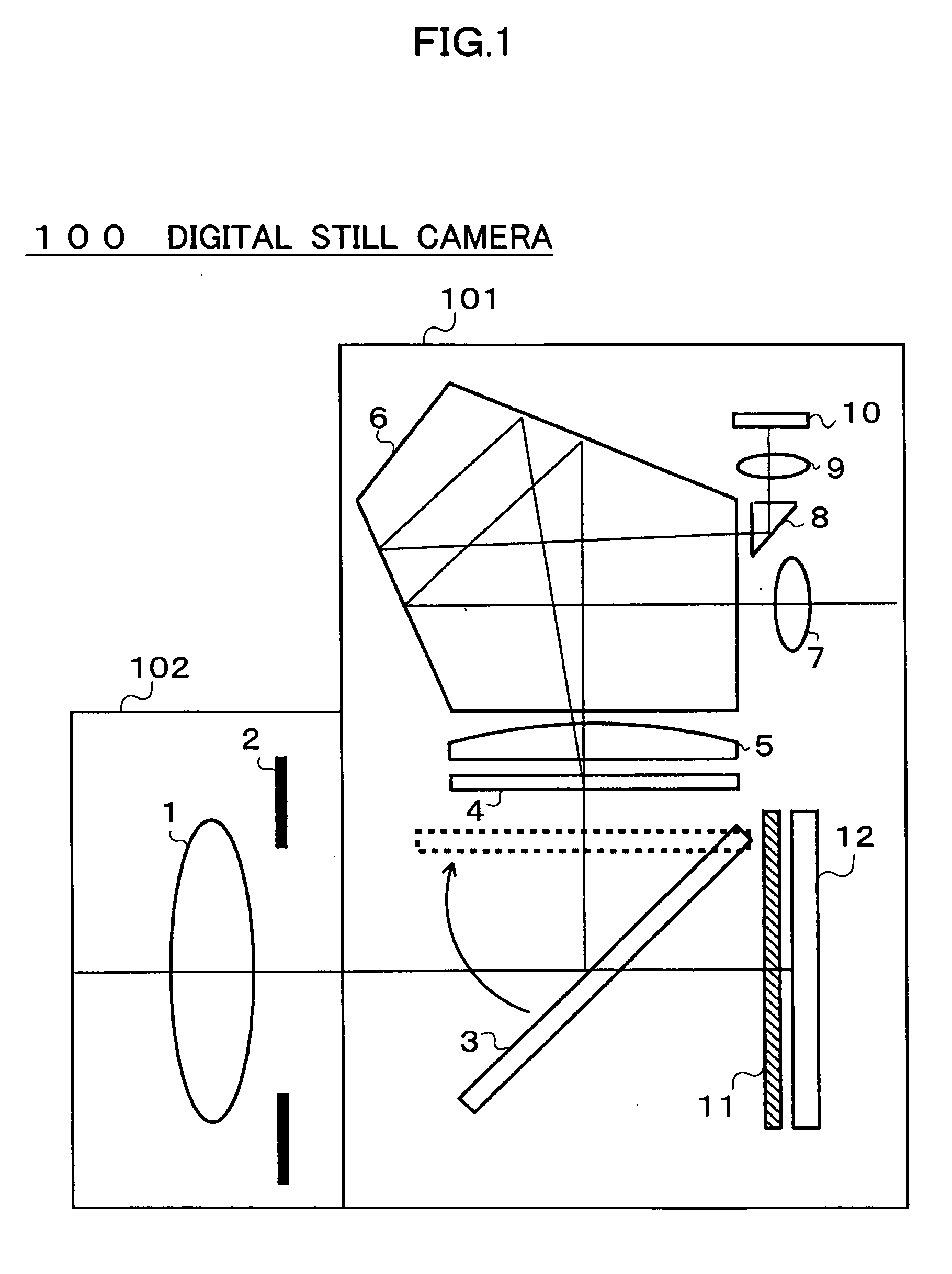
[0034]FIG. 1 is a schematic block diagram of a digital still camera 100 according to the first embodiment. The digital still camera 100 is composed of a camera body 101 and a shooting lens 102. The shooting lens 102 can be detachably mounted on the camera body 101, and has a lens 1 and an aperture stop 2 inside. Incidentally, shooting lenses other than the shooting lens 102 can also be detachably mounted on the camera body 101.

[0035] The camera body 101 is a single-lens reflex camera, including a quick return mirror 3, a diffusion screen 4 (focusing screen), a condensing lens 5, a pentaprism 6, an eyepiece 7, a photometry prism 8, a photometry lens 9, a photometry device 10, a shutter 11, and an image-capturing device 12.

[0036] During non-shooting, the quick return mirror 3 is arranged at an angle of 450 to an optical axis as shown in FIG. 1. Then, with the shooting le...

second embodiment

[0087] Hereinafter, a second embodiment of the present invention will be described in detail with reference to the drawings. The same functional blocks as those of the first embodiment will be described below by using the same reference numbers as in the first embodiment.

[0088]FIG. 6 is a functional block diagram of a computer 200 according to the second embodiment. As shown in FIG. 6, the computer 200 includes an image correcting unit 20 and a display unit 21, as well as a readout unit 22 which can receive data and the like from exterior. An image processing program of the present invention is stored in the computer 200 in advance. According to this image processing program, the computer 200 performs image correction.

[0089] In FIG. 6, the computer 200 is connected to an external digital still camera 300 through the readout unit 22. The computer 200 acquires image data captured by the digital still camera 300, corrects the image data in the image correcting unit 20 through the ste...

third embodiment

[0100] Hereinafter, the third embodiment of the present invention will be described with reference to the drawings.

[0101]FIG. 7 is a block diagram showing an example of configuration of a digital still camera 201 to which the present invention is applied.

[0102] An image-capturing device 211 is made of a charge coupled device (CCD), a complementary metal oxide semiconductor (CMOS), or the like. The image-capturing device 211 receives light that is incident through a not-shown lens, and performs photoelectric conversion. A picture signal obtained by the photoelectric conversion is output to an automatic gain control (AGC) 214. Incidentally, the amount of the light incident on the image-capturing device 211 at the time of capturing is adjusted by an automatic exposure adjusting unit 212 through control on a shutter speed and an aperture.

[0103] The automatic exposure adjusting unit 212 calculates a proper exposure from the result of photometry by a photometry device 213. Based on the...


PUM


Abstract

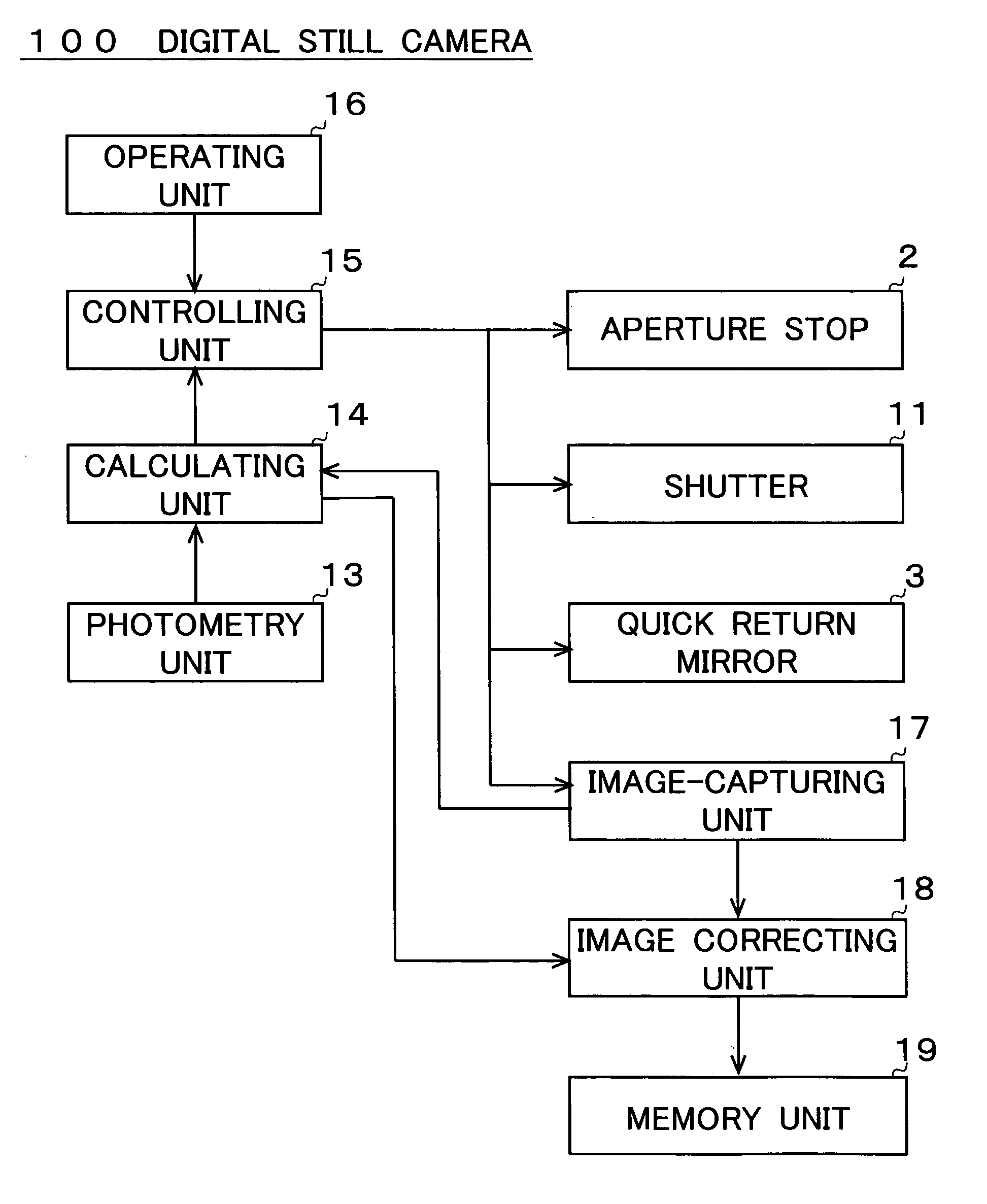
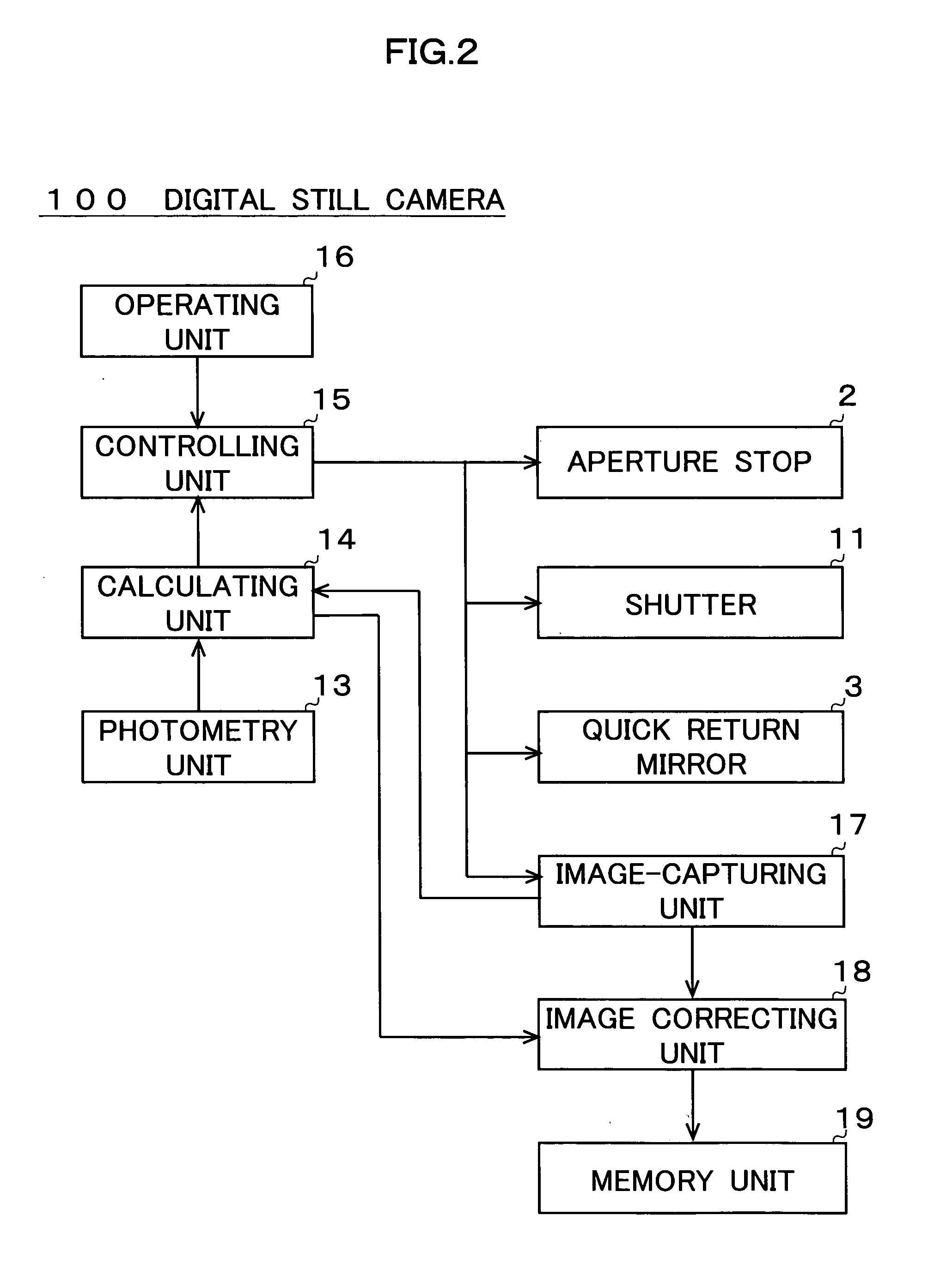
A digital still camera according to the present invention can obtain an image with appropriate brightness easily without an increase in memory capacity. The digital still camera of the present invention includes: an image-capturing unit which captures a field of object to generate an image; a photometry unit which measures a luminance of a predetermined area of the field of object; a calculating unit which calculates a ratio between a luminance value of a portion of the image captured according to the luminance measured by the photometry unit, and a target luminance value of the predetermined area, the portion corresponding to the predetermined area; and a correcting unit which corrects the image generated by the image-capturing unit according to the ratio.

Description

BACKGROUND OF THE INVENTION [0001] 1. Field of the Invention [0002] The present invention relates to a digital still camera which captures a field of object to generate an image, and to an image processing program for applying image processing to an image as well as an imaging device and a method and a program therefor. [0003] 2. Description of the Related Art [0004] Conventionally, a digital still camera measures the luminance of a field of object by using a photometry device or the like, and determine exposure, aperture, and other shooting conditions based on the result of measurement. Then, the digital still camera controls respective parts to achieve the determined conditions. However, errors may sometimes occur in such a control, failing to make an expected control according to the determined conditions. If the respective parts are not controlled according to the determined conditions, the resulting image may have loss of white gradation in highlight areas, loss of black gradat...

Claims


Application Information

Patent Timeline
Patent Type & Authority Applications(United States)
IPC IPC(8): H04N23/75
CPCH04N5/2351H04N9/735H04N5/2352H04N23/72H04N23/71H04N23/88
Inventor AOYAGI, HIDEHIKOMURAMATSU, MASARUHATTORI, YUKO
Owner NIKON CORP
Learn More