Collimator and spectrophotometer

Inactive Publication Date: 2005-09-22
NIRECO CORP
View PDF10 Cites 2 Cited by
  • Summary
  • Abstract
  • Description
  • Claims
  • Application Information

AI Technical Summary

Benefits of technology

[0016] An object of the present invention, which was developed in view of the above situation, is to provide a wavelength-independent compact collimator having high wavelength resolution, and to provide a compact spectrophotometer that uses this collimator and is capable of spectral measurement with high speed and high accuracy.
[0020] The collimator formed according to the present invention is configured such that a plurality of holes whose width is equal to the thickness of the aforementioned first metal sheets are formed in parallel, leaving open an interval equal to the thickness of the aforementioned second metal sheets. Specifically, a collimator is formed having a number of openings equal to the number of first metal sheets. The first metal sheets and second metal sheets are bonded by diffusion bonding based on thermocompression bonding, and can therefore be made sufficiently thin (specifically, their thickness may be on the order of tens of micrometers), and a collimator can thus be formed in which a large number of holes tens of micrometers wide are disposed at intervals of tens of micrometers.
[0025] Because of this, cutting may be performed until the cut portion reaches the holes in the first metal sheets during cutting, and there is no need to cut the portions of second metal sheets that comprise the barriers of the collimator holes (the holes are formed in advance) in the second metal sheets. These portions thus experience no deformation from the cutting force or heat during cutting.
[0027] The holes formed in the first metal sheets in the present means have grid members formed in the lengthwise direction, specifically, in the direction orthogonal with respect to the cutting planes thereof. These grid members serve as braces for supporting the second metal sheets that comprise the barriers of the collimator holes, and prevent deformation of the second metal sheets when the collimator is-completed, as later described in detail in the embodiments section using the figures. It is thus possible to obtain a collimator whose holes have a regular shape.

Problems solved by technology

However, a certain amount of space is needed to separate and guide the diffracted light in different directions according to wavelength when a prism, diffraction grating, or the like is used.
An unacceptably large spectrophotometer thus resulted.
Other drawbacks included the fact that the light intensity decreased due to the measured light being passed through a slit when guided to the prism or diffraction grating, and that high-speed measurement was difficult to accomplish because the storage time required for the linear sensor was considerable.
The following problems nonetheless exist in the system disclosed in Japanese Patent Application Laid-open No.
Specifically, multiple reflections occur between the linear variable filter and linear sensor due to these methods being configured such that the linear variable filter is attached to the linear sensor, and the spectral characteristics thus deteriorate.
While these problems are eliminated in the method disclosed in U.S. Pat. No. 6,057,925, other problems nonetheless occur.
However, such collimators have bulky structures, and it was believed to be impossible to manufacture a compact product that satisfies high resolution requirements and is capable of being used in transmission of light between a linear variable filter and a linear sensor.
Problems nonetheless exist in this method as well.
Consequently, high-resolution spectral results cannot be obtained for longer wavelengths (800 nm or greater).
It is costly and impractical to make an optical fiber corresponding to each wavelength.
Another drawback is that light transmissivity is attenuated when NA=0.35, even in a visible-range FOP.

Method used


Image

  • Collimator and spectrophotometer
  • Collimator and spectrophotometer
  • Collimator and spectrophotometer

Examples


Embodiment Construction

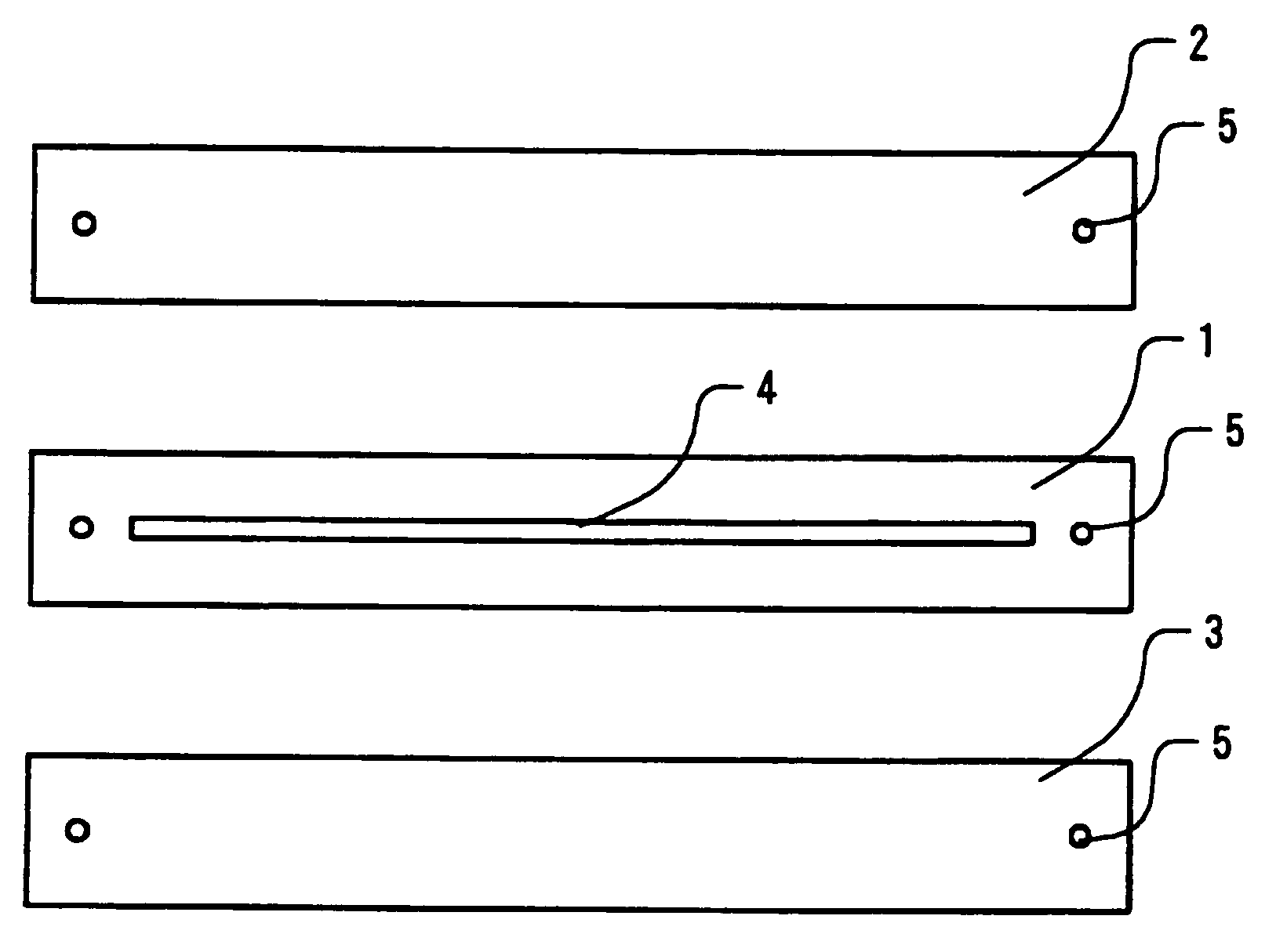
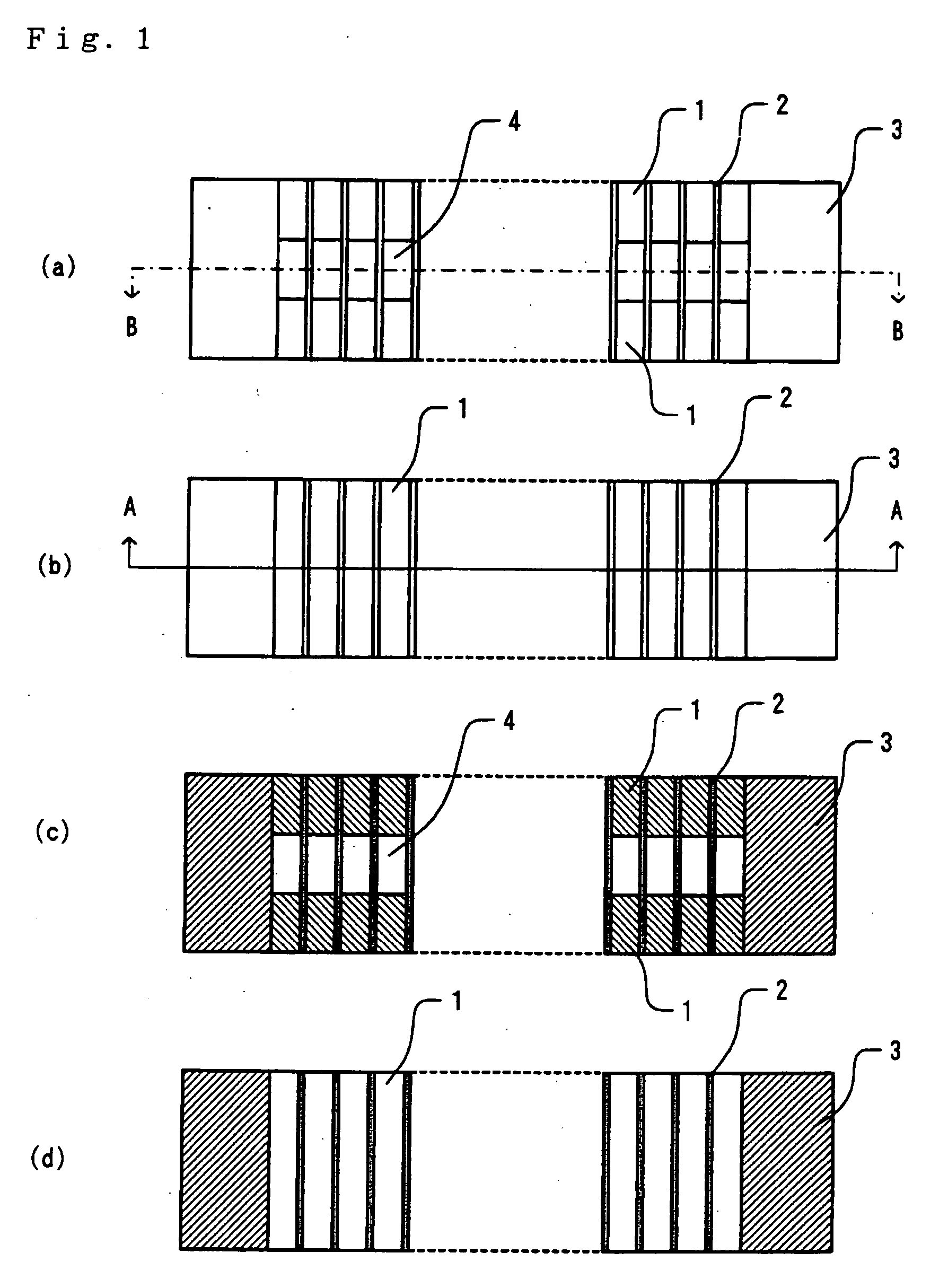
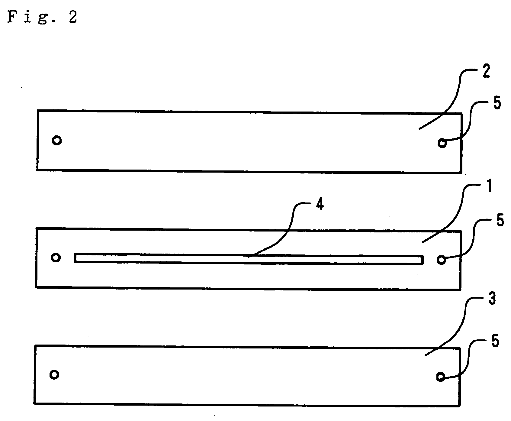
[0050] Embodiments of the present invention will be described hereafter using the figures. FIG. 1 is a diagram depicting a conceptual outline of the collimator according to the first example of the embodiments of the present invention. In FIG. 1, (a) is a plan view; (b) is a front view; (c) is an A-A cross-sectional view; and (d) is a B-B cross-sectional view. Because this figure is a conceptual diagram for describing the structure, the dimensions shown do not correspond to actual dimensions.

[0051] As is apparent from the diagram, the collimator is obtained by the alternate stacking of metal sheets 1 (40 μm thick) having holes 4 with a width of 2200 μm in the center thereof, and metal sheets 2 (10 μm thick) without holes (here, “the metal sheets 1 with the holes 4” describes in the state in which they exist before being cut in the manner described below, the upper portion and the bottom portion of the metal sheets 1 in the figure (in the finished product) are not connected with eac...


PUM

PropertyMeasurementUnit
Lengthaaaaaaaaaa
Lengthaaaaaaaaaa
Lengthaaaaaaaaaa

Abstract

A collimator obtained by the alternate stacking of metal sheets 1 (40 μm thick) having holes 4 with a width of 2200 μm in the center thereof, and metal sheets 2 (10 μm thick) devoid of holes (the metal sheets 1 with the holes 4 are shown in the state in which they exist before being cut in the manner described below, the metal sheets 1 in the upper portion of the figure and the metal sheets in the bottom portion are not connected with each other in the finished product). The opposite sides are held by metal pressing sheets 3 that are 2 mm thick. These metal sheets and pressing sheets are bonded by means of diffusion bonding based on thermocompression bonding. The portions with the vertical through-holes 4 (40 μm×2000 μm) thus become light-transmitting portions, the metal sheets 2 serve as partitions between adjacent holes 4, and light collimated to a width of 40 μm can ultimately pass through. A compact collimator having high wavelength resolution without wavelength dependence can thus be achieved.

Description

CROSS-REFERENCE TO RELATED APPLICATION [0001] The present application is a Divisional application of U.S. application Ser. No. 10 / 262,802, filed Oct. 2, 2002.BACKGROUND OF THE INVENTION [0002] 1. Field of the Invention [0003] The present invention relates to a high-performance collimator and compact spectrophotometer capable of performing spectrophotometry without using a prism or diffraction grating. [0004] 2. Description of the Related Art [0005] Conventionally, a method for measuring spectral intensity by guiding light in a different direction for each wavelength using a prism or a diffraction grating, irradiating the light to a linear sensor or the like, and measuring the output from the elements of the linear sensor was generally used to perform spectrophotometry. However, a certain amount of space is needed to separate and guide the diffracted light in different directions according to wavelength when a prism, diffraction grating, or the like is used. An unacceptably large spe...

Claims


Application Information

Patent Timeline
IPC IPC(8): G01J3/02G01J3/12G01J3/26G01J3/36G02B5/00G02B27/30
CPCG01J3/02G01J3/0208G01J3/12Y10T29/49789G02B27/30Y10T29/49826G02B5/00
Inventor YAMADA, TAKEOKOBAYASHI, TOMOYUKI
Owner NIRECO CORP
Why Eureka
Try Eureka