Photoelectric encoder and method of manufacturing scales

a technology of encoder and scale, applied in the field of photoelectric encoder, can solve problems such as preventing improvements in measurement accuracy, and achieve the effect of improving controllability

Inactive Publication Date: 2005-09-22
MITUTOYO CORP
View PDF8 Cites 21 Cited by
  • Summary
  • Abstract
  • Description
  • Claims
  • Application Information

AI Technical Summary

Benefits of technology

[0019] The method of manufacturing the scale according to the present invention may further comprise, between the step of forming the second metal layer and the step of forming the reflective optical grating, the steps of: forming a third metal layer containing the one of chromium and tungsten on the second metal layer: and selectively etching the third metal layer with an etching stopper of the second metal layer, wherein the step of forming the reflective optical grating includes selectively etching the second metal layer with a mask of the third metal layer. In this case, the optical grating has a depressed surface (the first metal layer) and a projected surface (the third metal layer) of the same material. Therefore, it is possible to produce a scale having an optical grating with a uniform optical reflectance. In addition, the second metal layer is etched with a mask of the third metal layer. Accordingly, no mask matching is required and the controllability can be improved over the processed shape of the optical grating.

Problems solved by technology

As the optical signal to be received at the photo receiver to generated from the optical grating on the scale, the above variations prevent improvements in the measurement accuracy.

Method used


Image

  • Photoelectric encoder and method of manufacturing scales
  • Photoelectric encoder and method of manufacturing scales
  • Photoelectric encoder and method of manufacturing scales

Examples


first embodiment

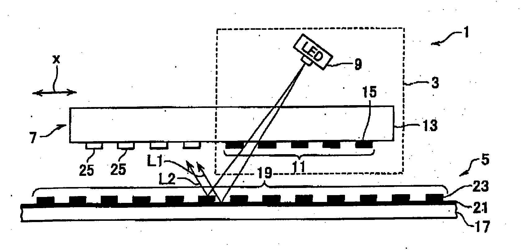
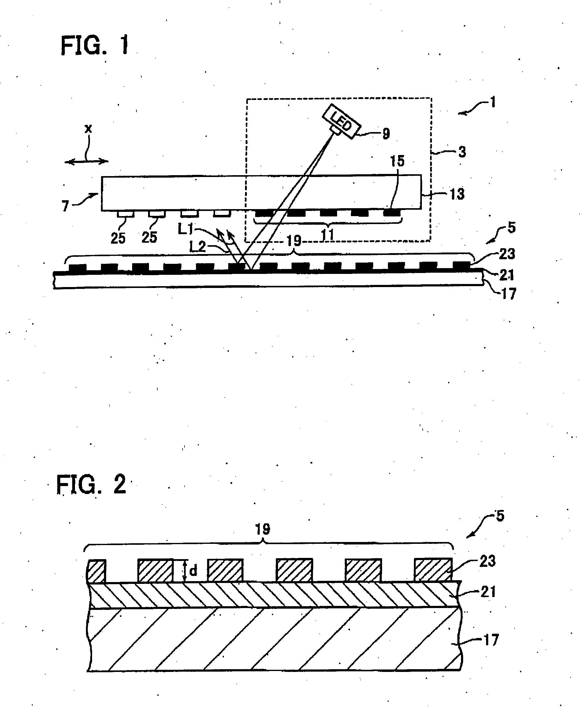
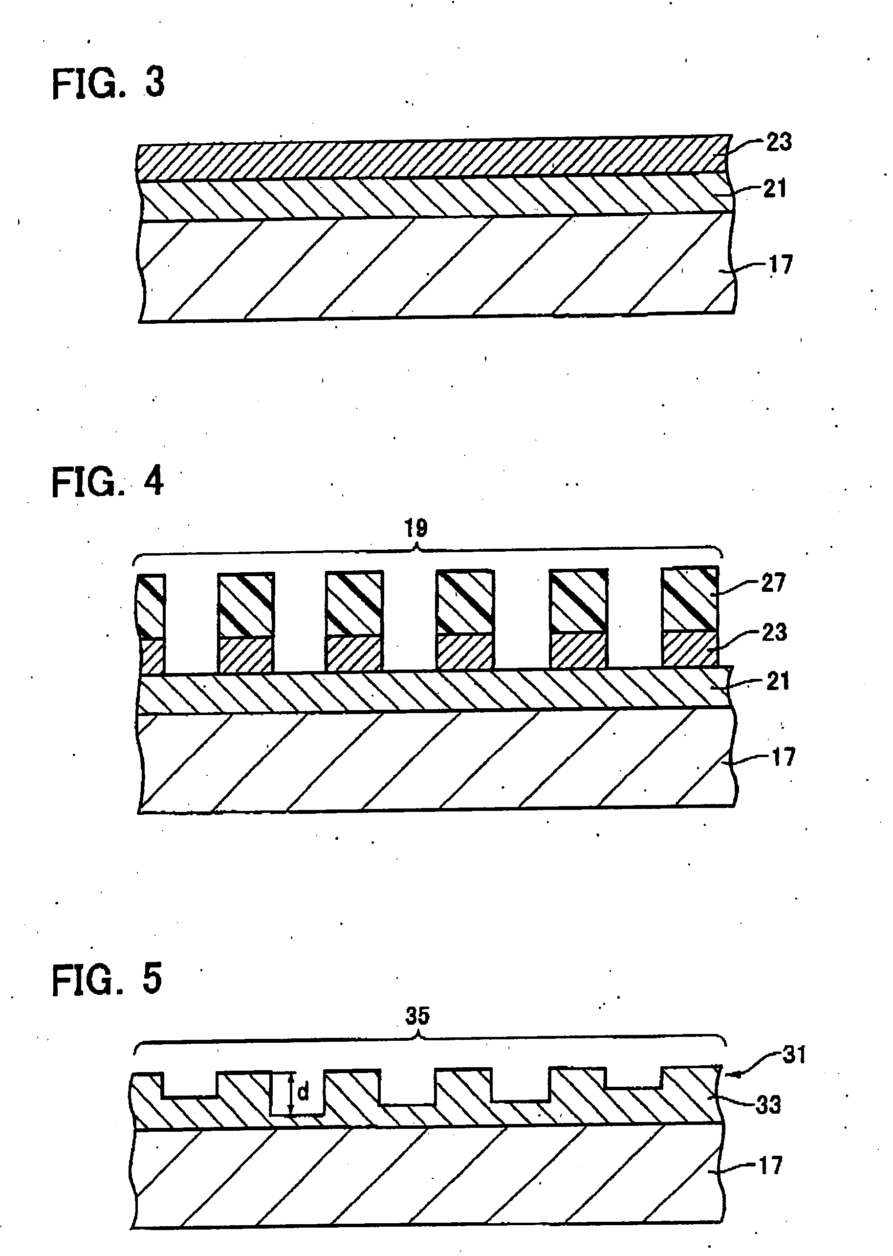
[0031] A first embodiment is mainly characterized by a reflective optical grating arranged on a scale in a photoelectric encoder. The grating includes a first metal layer (tungsten), and a second metal layer (chromium) having a plurality of portions formed on the first metal layer and arrayed at a certain pitch. First, the photoelectric encoder 1 according to the first embodiment is described about structure thereof. FIG. 1 illustrates a brief structure of the photoelectric encoder 1. The photoelectric encoder 1 comprises a light source 3, a scale 5 with an optical grating that is exposed to light emitted from the light source, and a photo receiver 7 arranged to receive light reflected from the optical grating.

[0032] The light source 3 includes a light-emitting diode (LED) 9. The light source 3 also includes an index grating 11 located at a position that is exposed to light from the light-emitting diode 9. The index grating 11 is formed on one of surfaces of an elongated transparen...

second embodiment

[0049] A second embodiment is mainly characterized by a reflective optical grating arranged on a scale in a photoelectric encoder. The grating includes a first metal layer (chromium), a second metal layer (tungsten) having a plurality of portions formed on the first metal layer and arrayed at a pitch, and a third metal layer (chromium) having a plurality of portions formed on the portions of the second metal layer. The second embodiment is described mainly on differences from the first embodiment. The same parts in the figures illustrative of the second embodiment as those in the figures illustrative of the first embodiment are given the same reference numerals to omit their duplicate description.

[0050]FIG. 6 is an enlarged cross-sectional view of part of the scale 5 according to the second embodiment, which corresponds to FIG. 2. The portions of the third metal layer 29 are formed on the portions of the second metal layer 23. The first metal layer 21 is composed of a material of c...

third embodiment

[0055]FIG. 9 is an enlarged cross-sectional view of part of a scale 5 according to a third embodiment. The third embodiment is characterized in that an optical grating 19, or a phase grating, has a sidewall angle (edge angle) θ larger than 80 degrees and smaller than 90 degrees. The scale 5 according to the third embodiment is made on the basis of experiments performed by the Inventor(s) of the present invention et al.

[0056] Preferably, the optical grating 19 can achieve higher diffraction efficiency and is robust against variations in grating shape and dimension. The Inventor(s) et al. employ a commercially available program for simulation of the diffraction effect to obtain the shape and dimension of the optical grating that can achieve such the affect.

[0057] The scale 5 employed in the simulation is described with reference to FIG. 9. On the surface of a substrate 17 composed of glass, a first metal layer 21 serving as a reflecting film is disposed. Only on the upper surface of...


PUM

PropertyMeasurementUnit
sidewall angleaaaaaaaaaa
thicknessaaaaaaaaaa

Abstract

A first metal layer of tungsten is formed on a substrate in a scale. A second metal layer of chromium is formed on the first metal layer. The second metal layer is selectively removed with a mask of resist and an etching stopper of the first metal layer to form an optical grating.

Description

CROSS-REFERENCE TO RELATED APPLICATION [0001] This application is based upon and claims the benefit of priority from the prior Japanese Patent Applications No. 2004-17567, filed on Jan. 26, 2004 and No. 2004-91344, filed on Mar. 26, 2004; the entire contents of which are incorporated herein by reference. BACKGROUND OF THE INVENTION [0002] 1. Field of the Invention [0003] The present invention relates to a photoelectric encoder for use in precise measurements and method of manufacturing a scale as an element of the photoelectric encoder. [0004] 2. Description of the Related Art [0005] A photo electric encoder (hereinafter, it may also be simply referred to as the “encoder”) has been employed in the art for precise measurements of linear displacements and angular displacements. The encoder may be mounted on a coordinate measuring machine and an image-measuring instrument. A brief description is given to a measurement by the photo electric encoder as follows. [0006] A light source and ...

Claims


Application Information

Patent Timeline
Patent Type & Authority Applications(United States)
IPC IPC(8): G01D5/347G01D5/38G02B5/18
CPCG01D5/34707G02B5/1857G01D5/38
Inventor KANNO, TAKASHITOMINAGA, ATSUSHIKOJIMA, KENICHI
Owner MITUTOYO CORP
Why Eureka
Try Eureka