Eureka AIR delivers breakthrough ideas for toughest innovation challenges, trusted by R&D personnel around the world.

Diagnostic mechanisms within multi processing systems

a multi-processing system and diagnostic mechanism technology, applied in the field of data processing systems, can solve problems such as general increase in problems, difficult to quickly and efficiently perform diagnostic operations on such integrated circuits, and difficult to diagnose operations more difficult, and achieve high speed

Active Publication Date: 2005-09-22
ARM LTD
View PDF0 Cites 8 Cited by
  • Summary
  • Abstract
  • Description
  • Claims
  • Application Information

AI Technical Summary

Benefits of technology

[0012] The present technique recognizes that within an integrated circuit it is possible to use a programmable processor which is provided for operational use to in fact perform diagnostic operations upon another data processing circuit within that integrated circuit if the programmable processor is given access to diagnostic data relating to the data processing circuit being subject to investigation. Thus, whilst the data processing circuit under investigation may, for example, be halted to provide halting mode debug, have taken an exception to provide monitor mode debug, or have been subject to code profiling diagnostic data capture whilst still executing program instructions, the processor being used to perform the diagnostic operations remains active and queries the captured diagnostic data on-chip using high speed and efficient communication mechanisms.
[0013] The halting of the data processing circuit being diagnosed is a beneficial diagnosis technique since it may be triggered and managed by the diagnostic circuit hardware in a manner which produces less alteration to the data processing circuit being investigated and accordingly tends to give more accurate diagnostic results. The halting mechanism does however require processing by the data processing circuit being diagnosed to be stopped and this can preclude certain real time investigations.
[0016] As well as debugging the data processing circuit on-chip, the processor accessing the captured diagnostic data relating to the data processing circuit may also control output of that diagnostic data using the communication mechanisms normally provided for operational purposes and optionally pre-process the captured diagnostic prior to output or other use (e.g. compress or transform to a higher level representation). Thus, high speed diagnostic data output may be supported without requiring dedicated diagnostic data pins.
[0017] A further advantage of not requiring a dedicated diagnostic interface (e.g. JTAG) is that it may not be necessary to use a custom device (i.e. a protocol translator) for communication between a development system (e.g. a workstation running a debugger) with this diagnostic interface.
[0020] It is convenient to provide the processor with access to the diagnostic data relating to the data processing circuit under investigation by providing such diagnostic data within memory mapped storage locations which are accessible to the processor. Typically the storage locations will form part of the physical memory associated with the integrated circuit but may instead be special purpose diagnostic registers which happen to be addressed using memory mapped locations.
[0022] External communication of diagnostic data may be enhanced by use of a peripheral device communication circuit normally provided for non-diagnostic operation, such as an operational Ethernet peripheral device.

Problems solved by technology

The provision of multiple processing circuits within a single integrated circuit makes such diagnostic operations more difficult due to the increase in complexity whilst maintaining the low package pin count which it is normally desired to dedicate to diagnostic operations.
With complex multi-processor systems such scan chains will accordingly become long and this, coupled with the relatively slow speeds at which it is possible to serially scan using such external debugging mechanisms, results in difficulty in rapidly and efficiently performing diagnostic operations upon such integrated circuits.
These problems are generally increasing as the complexity and number of processors and processing circuits within integrated circuits steadily increases and the normal operation speeds of those integrated circuits increase whilst the diagnostic capabilities and diagnostic speeds of serial scan chains remain relatively limited.
The overhead of a required protocol translator is also a disadvantage.
This requires disadvantageous operating system support and is also intrusive upon normal operation.

Method used


Image

  • Diagnostic mechanisms within multi processing systems
  • Diagnostic mechanisms within multi processing systems
  • Diagnostic mechanisms within multi processing systems

Examples


Embodiment Construction

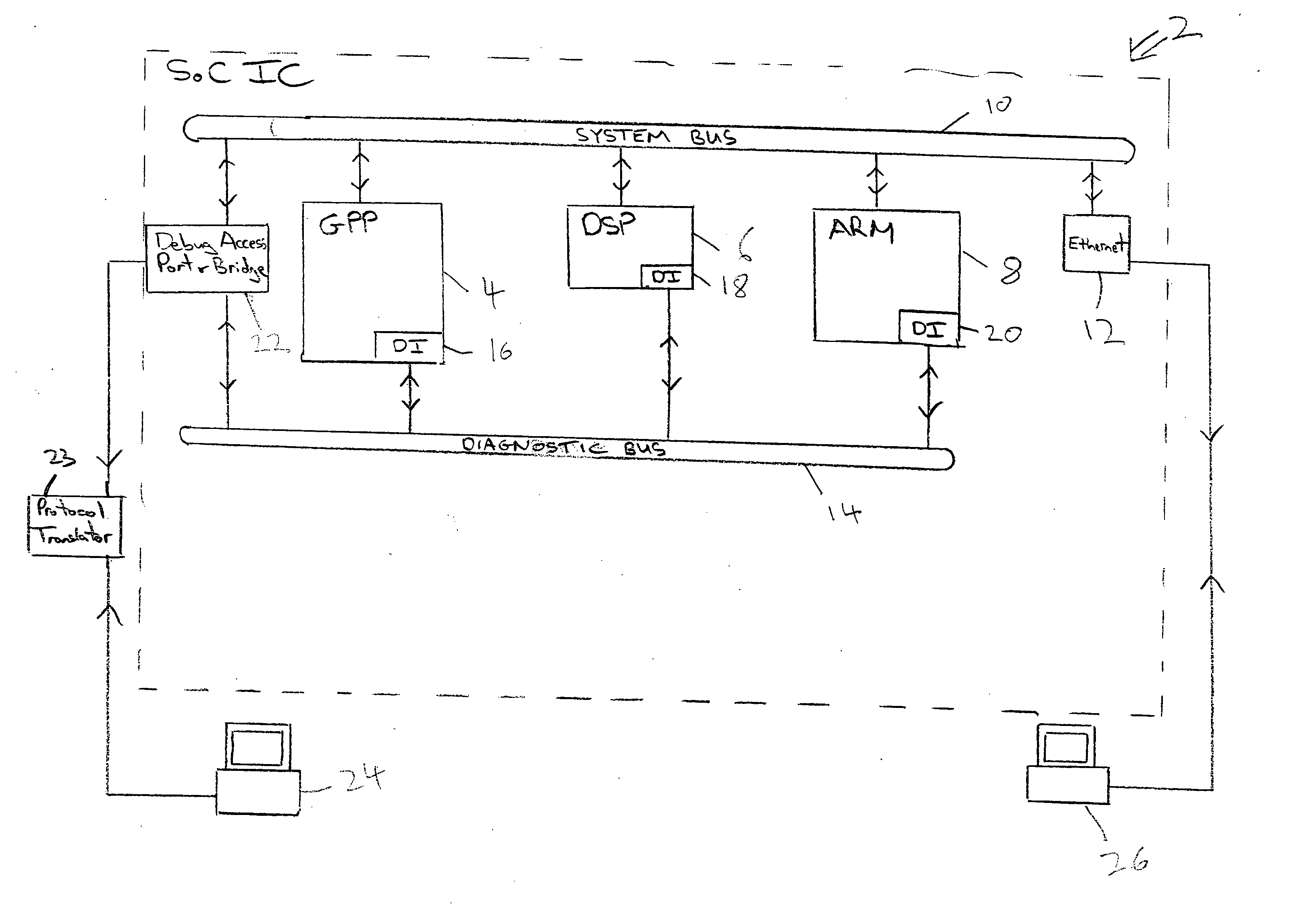
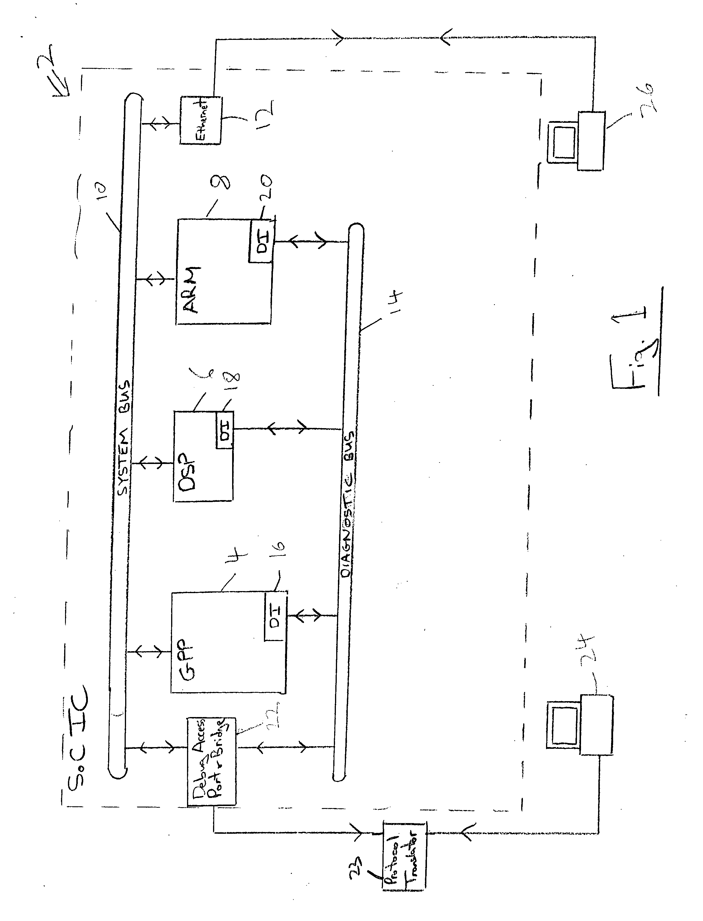
[0036]FIG. 1 schematically illustrates an integrated circuit 2 of a system-on-chip nature including a first general purpose processor 4, a DSP processor 6 and a second general purpose processor 8 coupled via a system bus 10 to perform non-diagnostic operations including external communication via an Ethernet peripheral circuit 12. A diagnostic bus 14 is also provided between diagnostic circuits 16, 18, 20 associated with respective ones of each of the first processor 4, the DSP processor 6 and the second processor 8. A bus bridge and diagnostic access port 22 is provided between the diagnostic bus 14 and the system bus 10 and also provides external communication via a protocol translator 23 to an external diagnostic device 24. The protocol translator 23 is not required in some preferred embodiments relying on other in-built communications mechanisms.

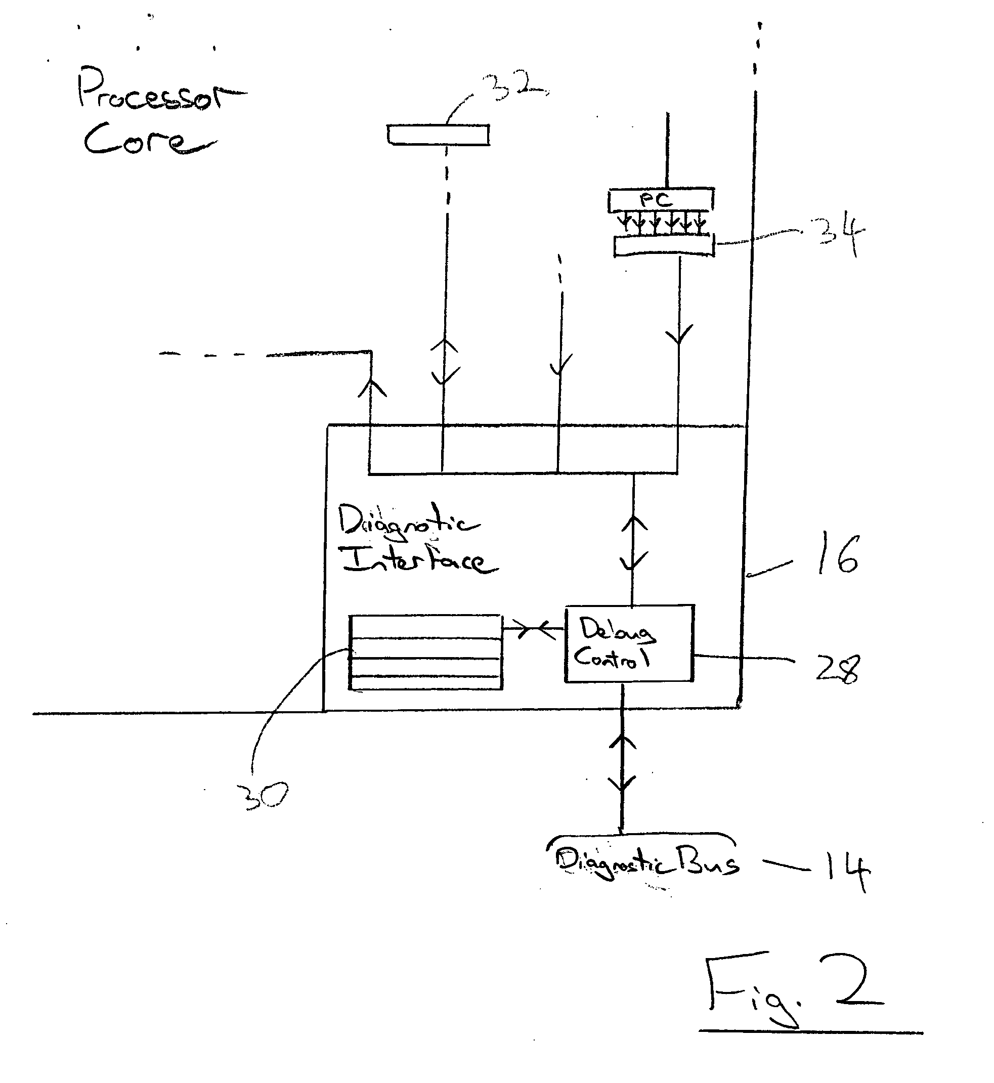
[0037] The diagnostic circuits 16, 18, 20 are operable to perform diagnostic operations upon their associated operational circuits 4, ...


PUM


Abstract

Within a system-on-chip device 2 having multiple processing circuits 4, 6, 8, one processing circuit 4 may serve to perform diagnostic operations upon another processing circuit 8 by accessing diagnostic data relating to that other circuit. Thus, one processor may, for example, control and perform halting mode type diagnostic or code profiling upon another.

Description

BACKGROUND OF THE INVENTION [0001] 1. Field of the Invention [0002] This invention relates to the field of data processing systems. More particularly, this invention relates to diagnostic mechanisms useful in performing diagnostic operations upon multi-processing systems. [0003] 2. Description of the Prior Art [0004] It is known to provide integrated circuits including more than one processor for performing data processing operations all combined within a single integrated circuit. Combining processors in this way reduces cost, reduces power consumption and increases speed. Such highly integrated designs are sometimes referred to as system-on-chip integrated circuits. The processors can take a wide variety of different forms such as general purpose processors, DSP elements, data engines and the like. [0005] When such complex, highly integrated systems are produced there is a strong need for efficient diagnostic mechanism such that bugs within their design and operation can be quickl...

Claims


Application Information

Patent Timeline
Patent Type & Authority Applications(United States)
IPC IPC(8): G06F11/00G06F11/07
CPCG06F11/079G06F11/0724G06F11/366
Inventor ALLUE, CONRADO BLASCOKIMELMAN, PAULSWAINE, ANDREW BROOKFIELDWILLIAMS, MICHAEL JOHN
Owner ARM LTD
Why Eureka
Eureka Blog
Learn More