Extreme ultraviolet exposure apparatus and vacuum chamber

a vacuum chamber and ultraviolet light technology, applied in the field of extreme ultraviolet light exposure apparatus and vacuum chamber, can solve the problems of extreme restriction and sacrifice of optical performance, and achieve the effects of reducing the exhaust or leakage tim

Inactive Publication Date: 2005-09-29
NIKON CORP
View PDF14 Cites 9 Cited by
  • Summary
  • Abstract
  • Description
  • Claims
  • Application Information

AI Technical Summary

Benefits of technology

[0037] However, since the exhaust rate and leak rate vary according to the degree of vacuum, if only the maximum rates are optimized, the exhaust time or leak time is lengthened. In the present invention, on the other hand, the exhaust rate and leak rate can be controlled in accordance with the degree of vacuum; accordingly, the exhaust time and leak time can be shortened, so that the throughput of the apparatus can be increased.

Problems solved by technology

Meanwhile, if an attempt is made to design a projection optical system for EUV in order to obtain a higher resolution, the exposure field becomes smaller, so that the desired area cannot be exposed at one time.
However, in cases where six projection system mirrors 13 through 18 are held in such a optical housing, there is a possibility of mechanical interference between this projection system optical housing and the illumination system mirror 12; accordingly, disposition is difficult, and even in cases where such disposition is possible, the problem of an extremely restricted disposition remains.
Furthermore, in cases where a disposition that is devised to avoid mechanical interference is used, there is a problem in that the optical performance must be sacrificed to some extent.

Method used


Image

  • Extreme ultraviolet exposure apparatus and vacuum chamber
  • Extreme ultraviolet exposure apparatus and vacuum chamber
  • Extreme ultraviolet exposure apparatus and vacuum chamber

Examples


Embodiment Construction

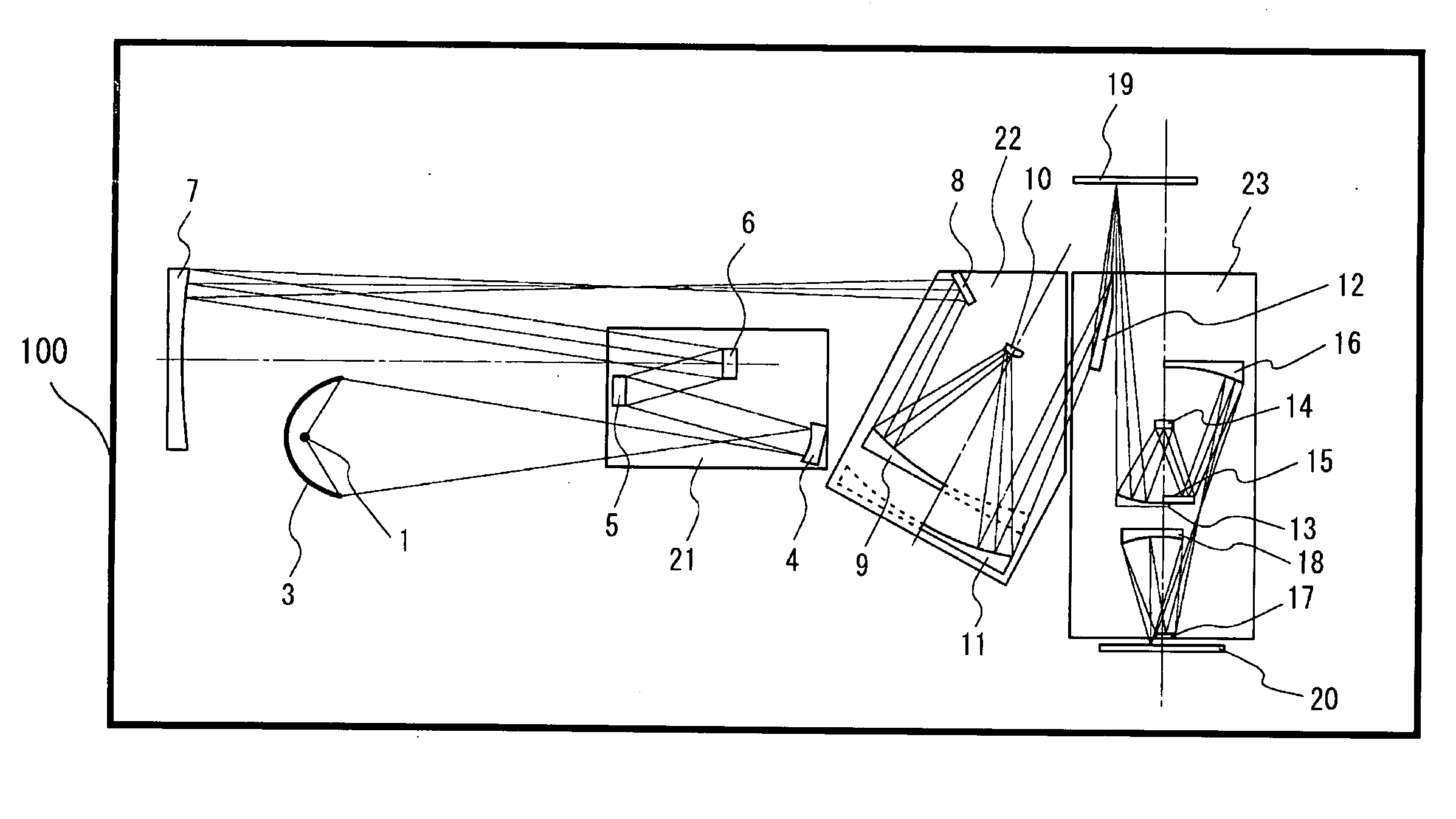
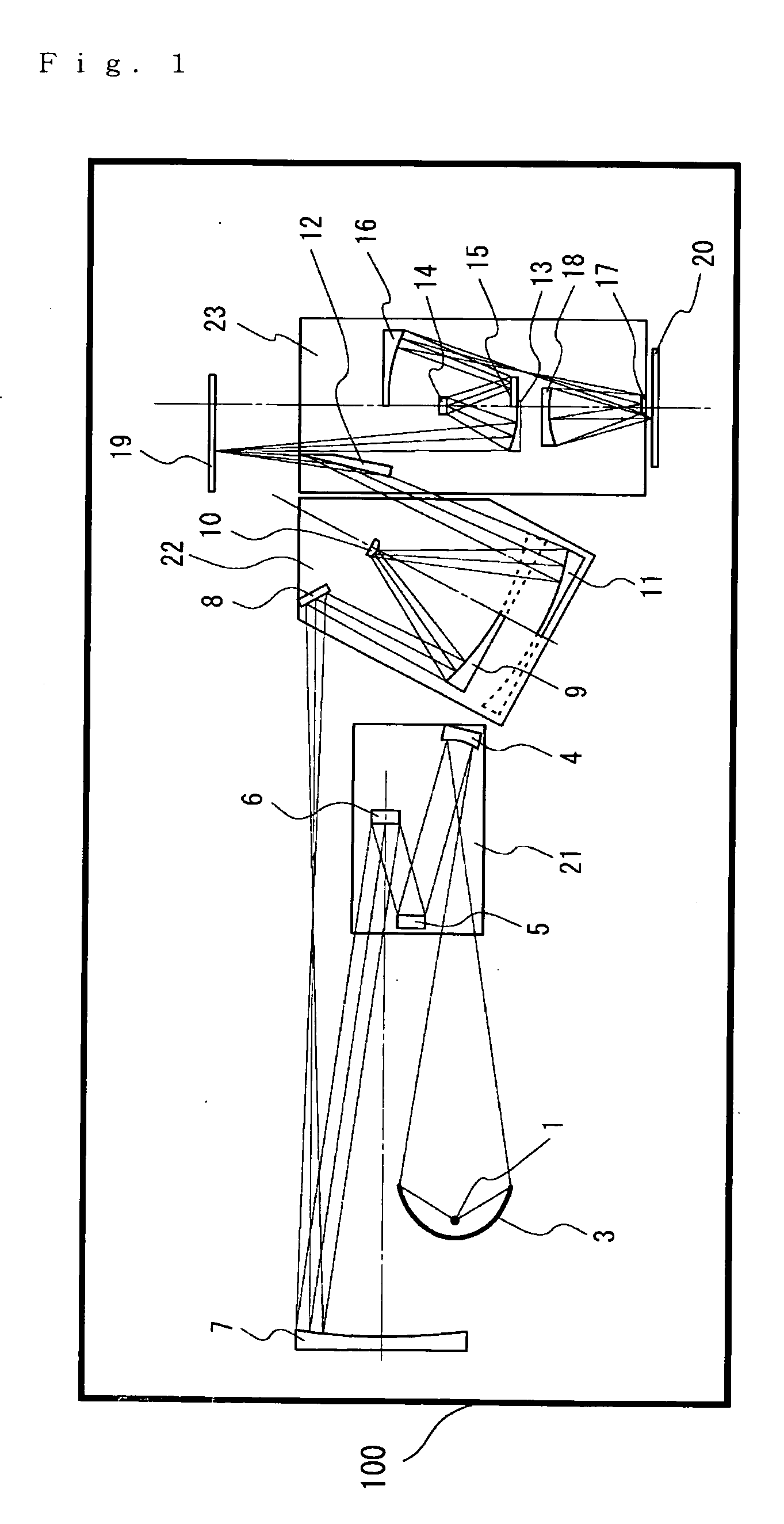
[0044] Working configurations of the present invention will be described below with reference to the figures. FIG. 1 is a schematic diagram showing the construction of an extreme ultraviolet (EUV) exposure apparatus constituting a first working configuration of the present invention. The basic construction of the optical system in this construction is the same as that shown in FIG. 5. Accordingly, the same symbols are assigned to constituent elements that are the same as constituent elements in FIG. 5, and a description of the operation and the like of these constituent elements is omitted.

[0045] The mirrors 4, 5 and 6 that constitute the illumination system are mechanically held by holding means (not shown in the figure) inside a single illumination system optical housing 21, so that these mirrors are formed into a unit. The illumination system mirror 7 has a structure that is held alone. The illumination system mirrors 8 through 11 are formed into a unit by being mechanically hel...


PUM

PropertyMeasurementUnit
wavelengthaaaaaaaaaa

Abstract

An extreme ultraviolet exposure apparatus comprising a light source that emits extreme ultraviolet light, a plurality of illumination reflective mirrors that direct the extreme ultraviolet light emitted from the light source to a mask, a plurality of projection reflective mirrors that direct the extreme ultraviolet light reflected by the mask onto a sensitive substrate and that project and focus an image of the mask on this sensitive substrate, and a projection system optical housing that accommodates at least one of the projection reflective mirrors and at least one of the illumination reflective mirrors.

Description

[0001] This is a continuation-in-part from PCT International Application No. PCT / JP2003 / 013515 filed on Oct. 23, 2003, which is hereby incorporated.TECHNICAL FIELD [0002] The present invention relates to an extreme ultraviolet (EUV: light with a wavelength of 4.5 nm to 30 nm) exposure apparatus and a vacuum chamber equipped with an exposure apparatus. BACKGROUND ART [0003] In exposure apparatuses used in the manufacture of semiconductors, a circuit pattern formed on a mask surface that is used as an object plane is projected and transferred onto a substrate such as a wafer via an image focusing optical system. The substrate is coated with a resist, and the resist is made photosensitive by exposure, so that a resist pattern is obtained. [0004] The resolution w of an exposure apparatus is determined mainly by the exposure wavelength k and the numerical aperture NA of the image focusing optical system, and is expressed by the following equation:w=kλ / NA k: constant[0005] Accordingly, in...

Claims


Application Information

Patent Timeline
Patent Type & Authority Applications(United States)
IPC IPC(8): G03B27/54G03F7/20
CPCB82Y10/00G03F7/70825G03F7/70166
Inventor MURAKAMI, KATSUHIKO
Owner NIKON CORP
Why Eureka
Try Eureka