Wavelength dispersion compensating apparatus

a compensating apparatus and wavelength technology, applied in the field of wavelength dispersion (chromatic dispersion) compensating apparatus, can solve the problems of deteriorating signal quality in the system, distortion of pulse waveform, and high manufacturing cost of dispersion compensating fibers

Inactive Publication Date: 2005-09-29
FUJITSU LTD
View PDF4 Cites 19 Cited by
  • Summary
  • Abstract
  • Description
  • Claims
  • Application Information

AI Technical Summary

Benefits of technology

[0031] According to the wavelength dispersion compensating apparatus of the present invention, since the wavelength dispersion and the wavelength dispersion slope to be given to the input light can be varied independently, it becomes possible to reliably compensate for wavelength dispersion and wavelength dispersion slope of a WDM light which has been propagated through an optical fiber to be accumulated, over a wide wavelength band.

Problems solved by technology

However, wavelength dispersion, also known as “chromatic dispersion”, occurring in the optical fiber deteriorates the signal quality in the system.
As another example of optical pulse transmission, in the case where a signal light having wavelength components which are consecutive from blue to red is transmitted, the respective components are propagated through the optical fiber at different speeds, and thus the time-width of pulse waveform of the signal light is extended inside the optical fiber, resulting in the distortion of pulse waveform.
However, the dispersion compensating fiber is expensive in manufacturing cost, and it is necessary to make the fiber length thereof relatively long in order to sufficiently compensate for the wavelength dispersion occurring in the transmission path fiber.
Therefore, there are caused problems of a large optical loss, and a large size.
However, since the chirped fiber grating has a reflective band of very narrow wavelength width, it is difficult to realize a sufficient reflective band for compensating for wavelength dispersion of a light containing a large number of wavelengths such as a WDM light.
However, there is a problem in that a system applying such a reciprocal dispersion component is expensive.
However, such third-order wavelength dispersion can be neglected since it presents very few problems at a transmission speed of approximately 40 Gb / s.
Moreover, in the case of WDM transmission, it is insufficient even if only the wavelength dispersion can be compensated as described above, and the wavelength dispersion slope also becomes problematic.
This is because, even if the dispersion can be compensated with a wavelength of a given signal channel, if the wavelength dispersion of the reciprocal dispersion component is constant, the wavelength dispersion cannot be compensated completely with a wavelength of a different signal channel.
However, although the wavelength dispersion can be set to be variable within a required range by the conventional reciprocal dispersion component as described above, it cannot have been realized that the wavelength dispersion and the wavelength dispersion slope are varied independently, as described above.
Therefore, such a dispersion compensating fiber is not practical.
Moreover, as described above, such a dispersion compensating fiber has problems of high cost, large loss, large size and the like.
Therefore, such a chirped fiber grating is not practical.
Additionally, as described above, it is also hard for the chirped fiber grating to obtain the sufficient wavelength bandwidth for compensating for the light having a large number of wavelengths such as WDM light.
However, since there is a limit in the angular dispersion obtainable within practical dimensions of typical diffraction gratings other than the VIPA, it is difficult to give the sufficiently large angular dispersion capable to compensate for the wavelength dispersion of relatively large value, which occurs in the optical fiber communication system.
Therefore, such a reciprocal dispersion component is not practical.

Method used


Image

  • Wavelength dispersion compensating apparatus
  • Wavelength dispersion compensating apparatus
  • Wavelength dispersion compensating apparatus

Examples


first embodiment

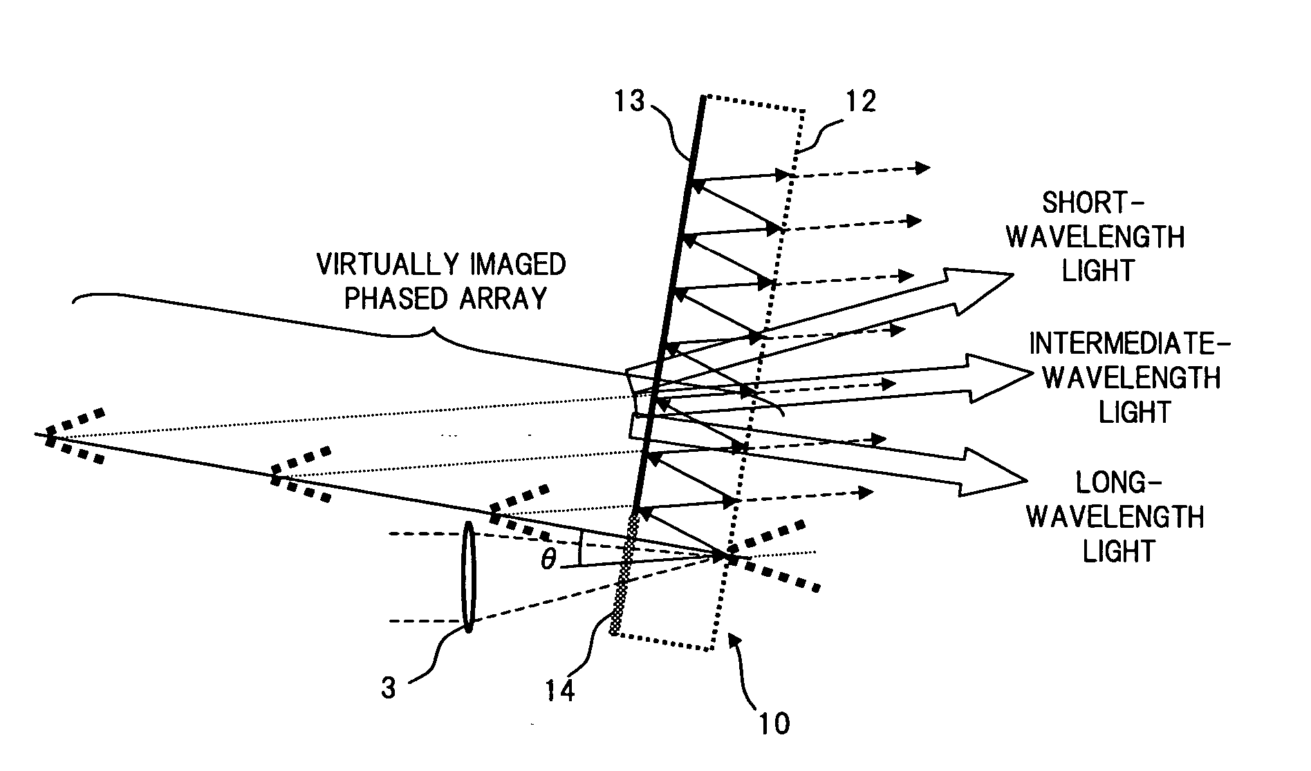
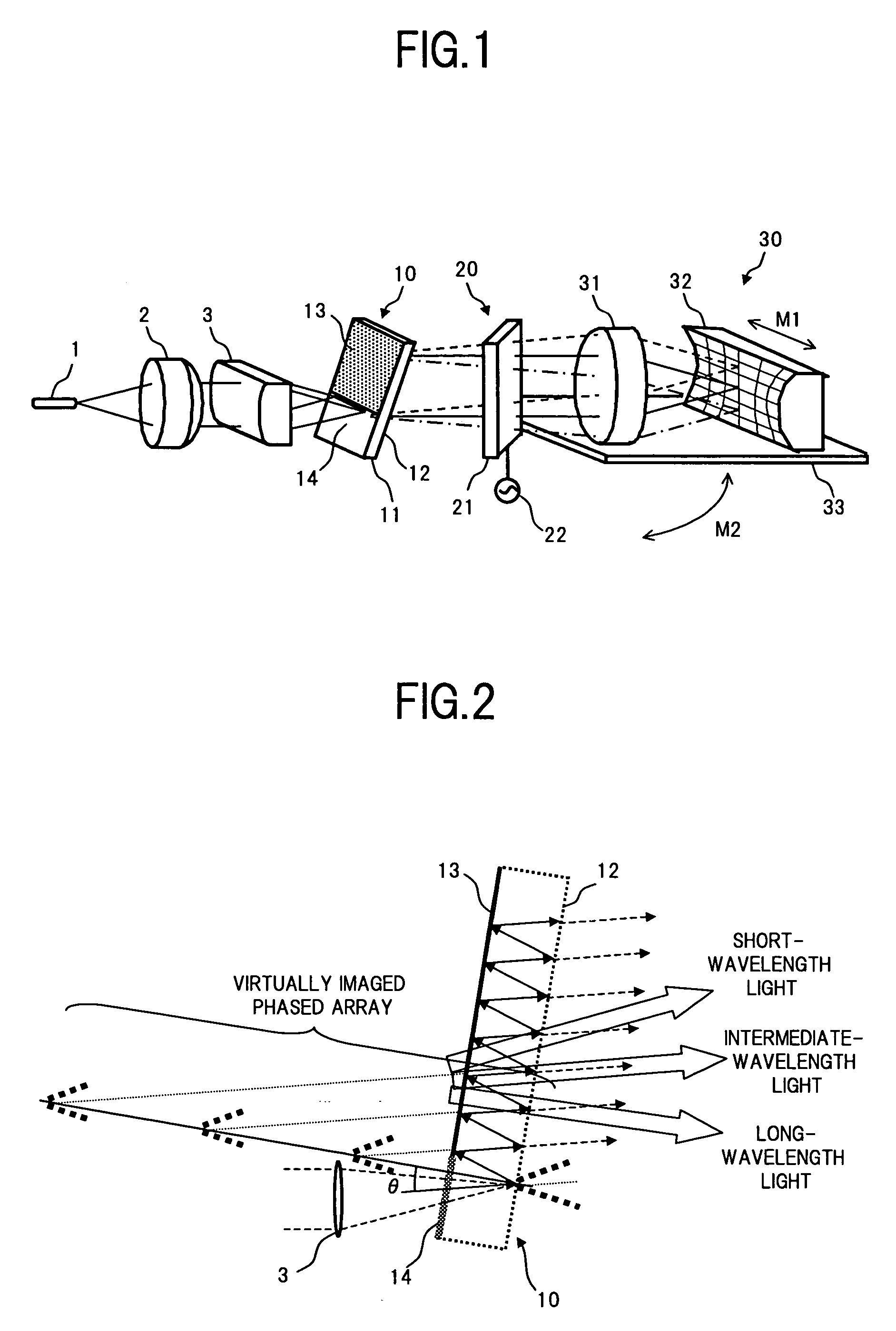
[0053]FIG. 1 is a perspective view showing a configuration of a wavelength dispersion (chromatic dispersion) compensating apparatus according to the present invention.

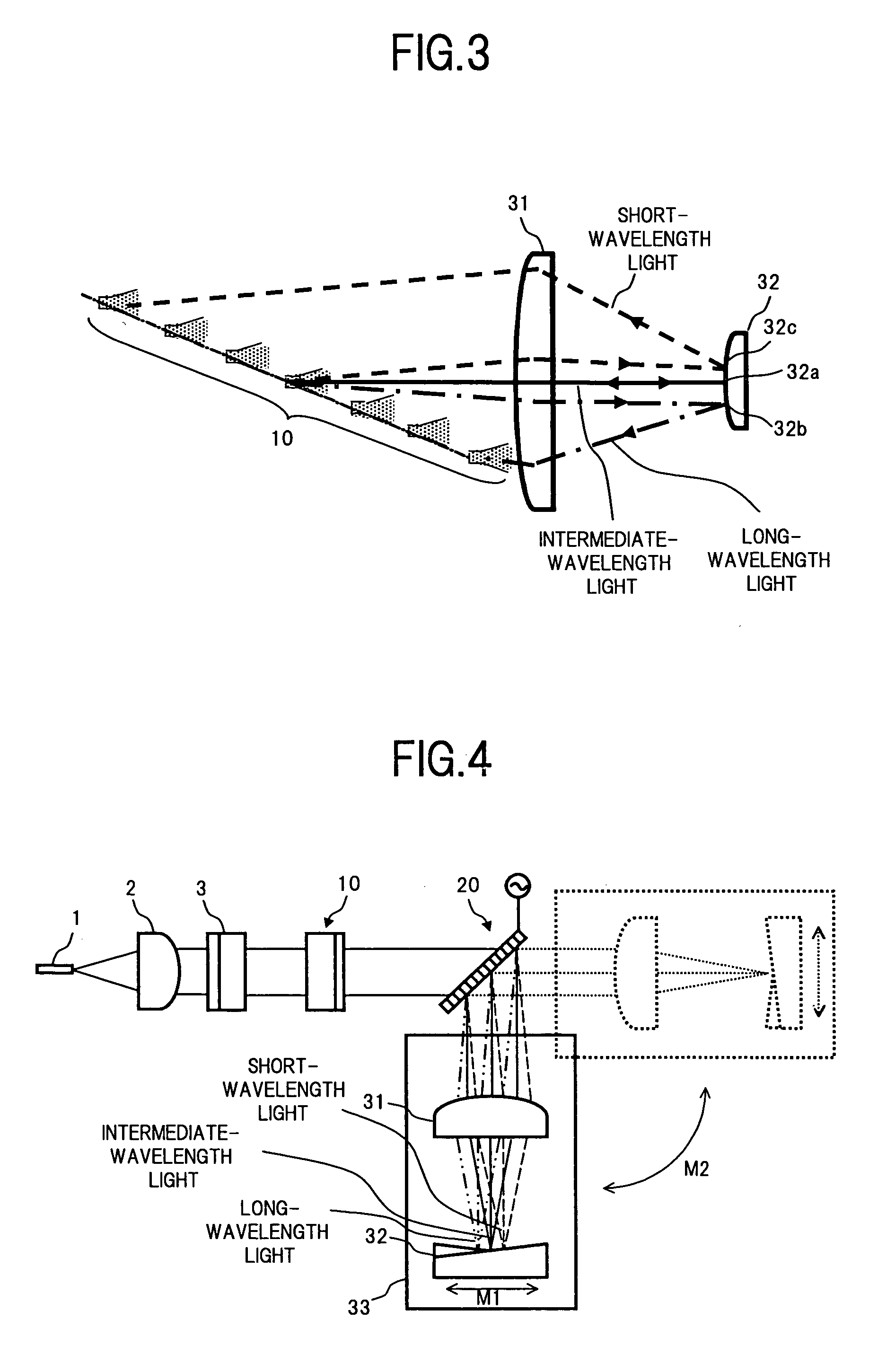
[0054] In FIG. 1, the wavelength dispersion compensating apparatus of the present embodiment comprises for example: a VIPA plate 10; an optical system consisting of an optical fiber 1, a collimate lens 2, and a cylindrical lens 3, which permits a WDM light condensed on one segment to be incident on a transmission area 14 of the VIPA plate 10; a variable dispersion diffraction grating 20 which is given with a light multi-reflected by the VIPA plate 10 and emitted from one of planes of the VIPA plate 10; and a light return apparatus 30 which reflects the light which has passed through the variable dispersion diffraction grating 20 and returns it to the VIPA plate 10 via the variable dispersion diffraction grating 20.

[0055] As with the conventional configuration shown in the above described FIG. 18, the VIPA plate 10 has...


PUM


Abstract

A wavelength dispersion compensating apparatus of the invention comprises: a VIPA plate capable to output incident lights at different angles according to wavelengths; a variable dispersion diffraction grating which can angularly disperse the lights of respective wavelengths output from the VIPA plate, in a direction substantially perpendicular to a direction of angular dispersion in the VIPA plate and also capable to change an amount of the angular dispersion; a light return apparatus which condenses the output lights from the variable dispersion diffraction grating and reflects them by a mirror, to return them to the VIPA plate side; and a stage rotation mechanism which rotates a movable stage on which the lens and the mirror are mounted, according to a diffraction angle in the variable dispersion diffraction grating, so as to enable wavelength dispersion and wavelength dispersion slope to be given to a WDM light, to be changed independently. As a result, it becomes possible to compensate for, over a wide wavelength band, the wavelength dispersion and wavelength dispersion slope of the WDM light, which are propagated through an optical fiber to be accumulated.

Description

BACKGROUND OF THE INVENTION [0001] (1) Field of the Invention [0002] The present invention relates to a wavelength dispersion (chromatic dispersion) compensating apparatus for compensating for wavelength dispersion and wavelength dispersion slope occurring in signal lights of respective wavelengths transmitted on optical fibers, in an optical communication of a wavelength division multiplexing (WDM) system. [0003] (2) Description of the Related Art [0004] In a conventional optical fiber communication system for transmitting information using light, a transmitter sends out an optical pulse via an optical fiber to a receiver. However, wavelength dispersion, also known as “chromatic dispersion”, occurring in the optical fiber deteriorates the signal quality in the system. [0005] Specifically, due to wavelength dispersion characteristics of the optical fiber, propagation speed of a signal light in the optical fiber is dependent on a wavelength of the signal light. For example, when an o...

Claims


Application Information

Patent Timeline
Patent Type & Authority Applications(United States)
IPC IPC(8): G02B5/18G02B26/08G02B6/34G02B27/00
CPCG02B6/12007G02B6/29311H04B10/25133G02B6/29394G02B6/29395G02B6/29358
Inventor MITAMURA, NOBUAKIMARUYAMA, SHINJI
Owner FUJITSU LTD
Why Eureka
Try Eureka