Electro-optical device and electronic apparatus

a technology of optical devices and electronic devices, applied in the direction of identification means, instruments, casings/cabinets/drawers, etc., can solve the problems of difficult to secure an area for applying the above-mentioned double-sided adhesive tape, and achieve the effect of increasing the versatility of possible design, enhancing the degree of strength, and high heat release

Active Publication Date: 2005-09-29
TCL CHINA STAR OPTOELECTRONICS TECH CO LTD
View PDF6 Cites 35 Cited by
  • Summary
  • Abstract
  • Description
  • Claims
  • Application Information

AI Technical Summary

Benefits of technology

[0009] In such a manner, the electro-optical panel and the illumination device are supported by the metal frame, and thus these elements are integrally coupled with each other to form a module. The term “integrally coupled” as used herein refers to a condition wherein two objects are attached to each other so as not to easily separate form each other. The metal frame is made of the metal material, and thus the degree of strength can be secured even when it is formed by bending a thin plate. As such, the metal frame is formed by bending the thin plate made of the metal material, and thus the metal frame can be reduced in size. Further, the electro-optical panel and the illumination device are supported by the metal frame, and thus the entire module including the electro-optical panel and so on can be reduced in size. In addition, the metal frame is formed of the plurality of frames, and thus, by directly coupling the frames with each other, the electro-optical panel and the illumination device can be supported only by the metal frame. For this reason, even though the double-sided adhesive tape is not used to support the electro-optical panel and so on, the electro-optical panel and so on can be integrally supported. Accordingly, the entire module is reduced in size, and the area for applying the double-sided adhesive tape is reduced. Therefore, the reduction in reliability due to the area for applying the double-sided adhesive tape when the electro-optical panel or the like is supported can be suppressed, and thus reliability of the support can be enhanced. As a result, it has advantages in that the module can be reduced in size and reliability when the respective components constituting the module are integrally supported can be enhanced. Further, the frame is formed of the metal material, and thus a heat release effect increases owing to high thermal conductivity and heat generated in the illumination device can be released to an exterior. As a result, bad effects such as operational defects due to an excessive increase in temperature can be reduced. In addition, since the frame is formed of the metal material, the degree of strength of the entire module can be enhanced. As a result, even when a strong external force such as an external shock is applied, owing to the enhanced degree of strength, the device is hardly damaged.
[0017] Further, an electronic apparatus according to the present invention comprises an electro-optical device as described in any one of the above-mentioned aspects. Accordingly, an electronic apparatus having a compact electro-optical device with the enhanced degree of strength and high heat release effect can be implemented, without causing the integrally formed module to be separated. As such, since the compact electro-optical panel can be formed, the entire electronic apparatus can be compact. Further, as the electro-optical device is reduced in size, other portions have enough room, and thus the versatility of possible design can be increased and performance can be enhanced. Further, since there is no case in which the integrally formed module is separated, a high-quality electronic apparatus free from failures can be implemented. Further, since the electro-optical device has the enhanced degree of strength, even when the strong external force is applied thereto, the electronic apparatus can be hardly damaged. In addition, the electro-optical device has high heat release effect, operational defects or the like of the electro-optical device due to an excessive increase in temperature can be reduced. Therefore, a high-quality electronic apparatus can be implemented.

Problems solved by technology

However, in recent years, with the progress of the portable apparatus of reduced size, while a module including a liquid crystal display panel or the like reduced in size, a display unit of the liquid crystal display panel or the like becomes large in size for the purpose of visibility, which results in a problem in that it is difficult to secure an area for applying the above-mentioned double-sided adhesive tape.

Method used


Image

  • Electro-optical device and electronic apparatus
  • Electro-optical device and electronic apparatus
  • Electro-optical device and electronic apparatus

Examples


first embodiment

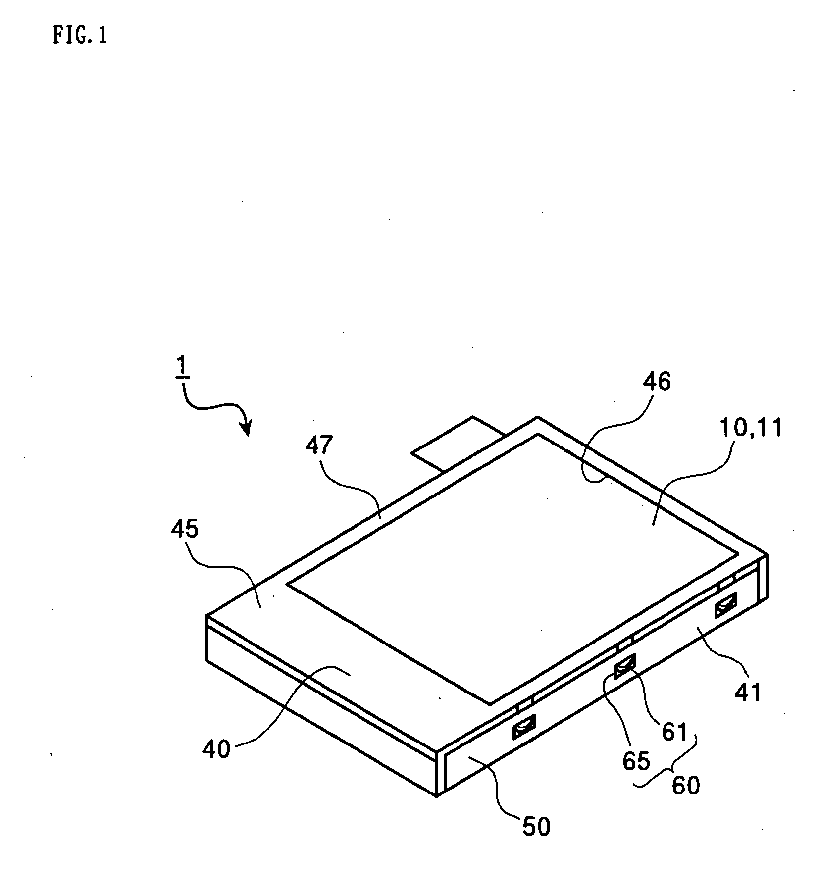
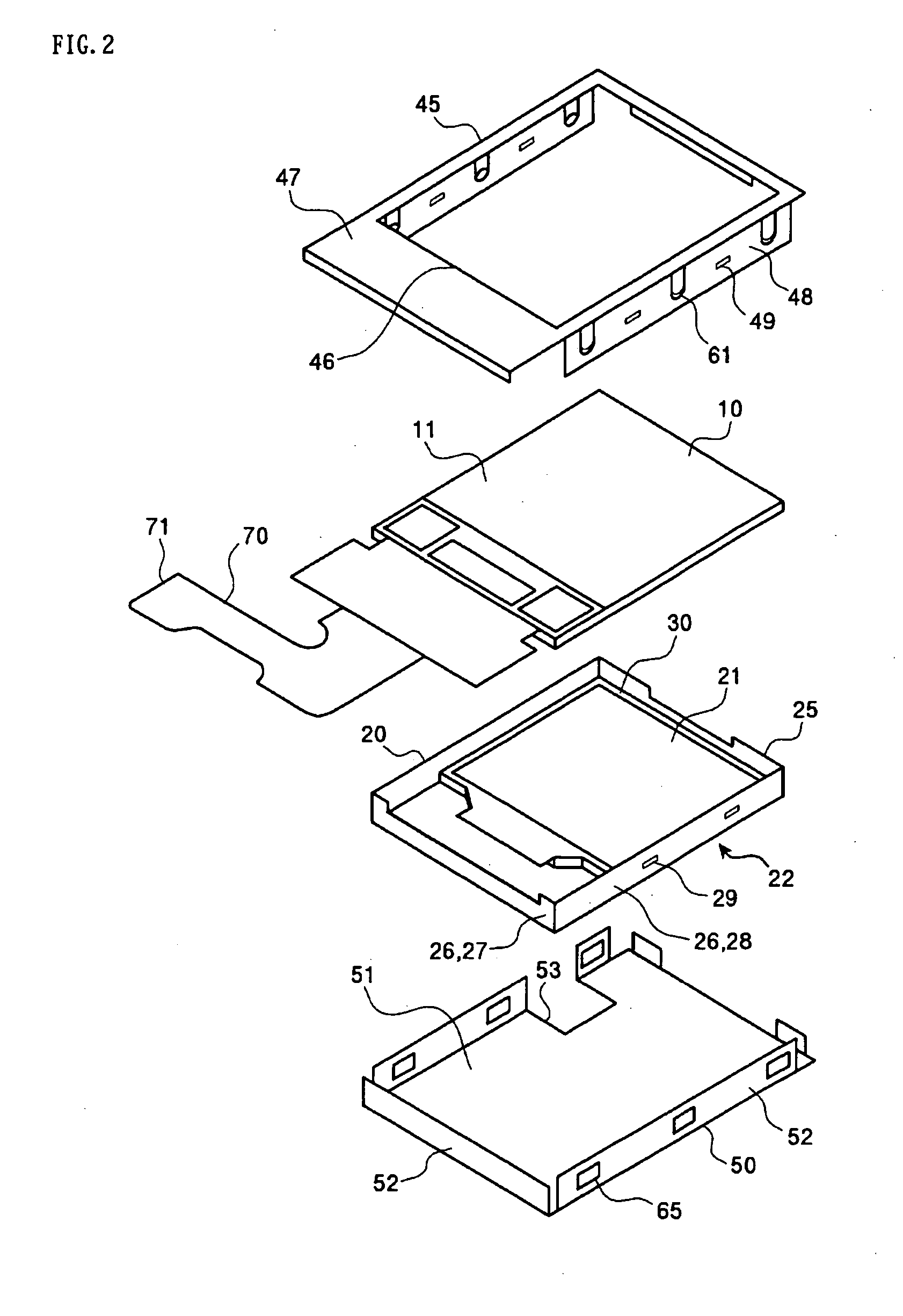
[0041]FIG. 1 is a perspective view showing a first embodiment of a liquid crystal display device according to the present invention. The liquid crystal display device 1, which is an example of an electro-optical device, is formed in such a manner that external main portions thereof are covered with a metal frame 40. In the metal frame 40, a liquid crystal display panel 10 serving as an electro-optical panel described below and a backlight unit 20 serving as an illumination device are housed. The metal frame 40 is made of a metal material such as stainless steel. Moreover, apart from stainless steel, the metal material may include aluminum, phosphor bronze, beryllium copper, or the like. The metal frame 40 has a first frame 45 and a second frame 50. The first frame 45 is positioned at an upper surface of the liquid crystal display device and the second frame 50 is positioned at a lower surface of the liquid crystal display device. Further, in the first frame 45, a rectangular display...

second embodiment

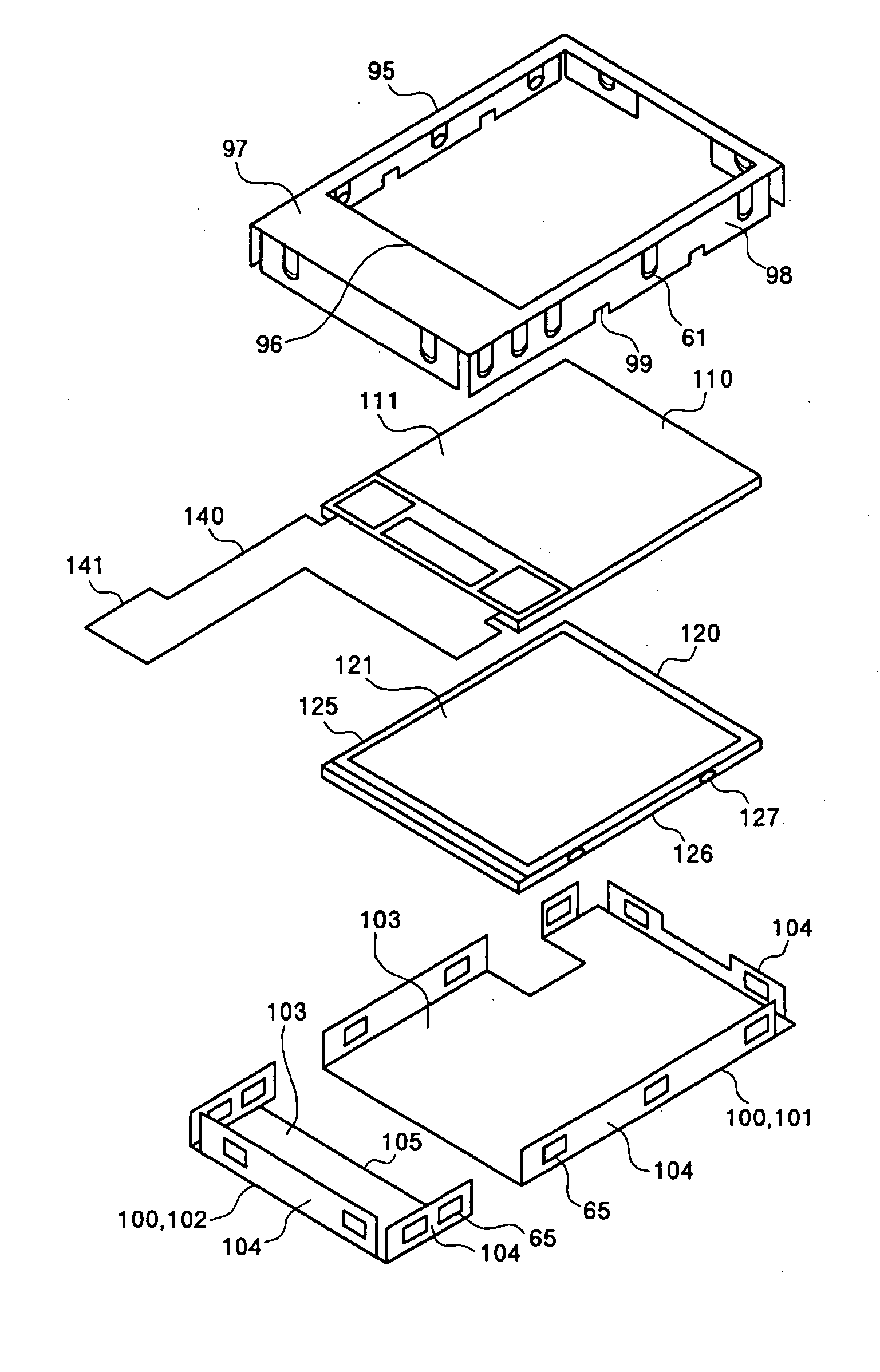
[0063] An electro-optical device according to a second example has a configuration approximately equal to that of the electro-optical device according to the first example, except that the second frame is divided into two portions. Other elements are the same as those in the first example, and thus the same elements are represented by the same reference numerals and the descriptions of the same elements will be omitted. FIG. 15 is a perspective view showing a second embodiment of a liquid crystal display device according to the present invention. A liquid crystal display device 80 of the second embodiment is formed such that external main portions thereof are covered with a metal frame 90, like the liquid crystal display device 1 of the first embodiment. In the metal frame 90, a liquid crystal display panel 110 and a backlight unit 120 are housed. While the metal frame 40 of the first example has the first frame 45 and the second frame 50, the metal frame 90 of the second example ha...

third embodiment

[0076] In a third embodiment, specified examples of an electronic apparatus having the electro-optical device described in the first or second embodiment will be described. FIGS. 20 to 22 show examples of an electronic apparatus in which the above-mentioned electro-optical device according to the present invention is mounted. FIG. 20 is a perspective view showing an example of a cellular phone. In FIG. 20, reference numeral 200 denotes a cellular phone main body, and reference numeral 201 denotes a display unit formed of the electro-optical device according to the present invention. FIG. 21 is a perspective view showing an example of a wristwatch-type electronic apparatus. In FIG. 21, reference numeral 210 denotes a watch main body having a watch function built-in, and reference numeral 211 denotes a display unit made of the electro-optical device according to the present invention. Then, FIG. 22 is a perspective view showing an example of a portable information processing device, s...


PUM

PropertyMeasurementUnit
elastic forceaaaaaaaaaa
flexibleaaaaaaaaaa
sizeaaaaaaaaaa

Abstract

An electro-optical device comprises an electro-optical panel in which an electro-optical material is arranged, an illumination device for radiating visible light onto the electro-optical panel, and a metal frame divided into a plurality of frames each being formed of a metal material, and the plurality of divided frames being integrally formed with each other such that the electro-optical panel and the illumination device are supported together.

Description

RELATED APPLICATIONS [0001] This application claims priority to Japanese Patent Application No. 2004-089408 filed Mar. 25, 2004 which is hereby expressly incorporated by reference herein in its-entirety. BACKGROUND [0002] 1. Technical Field [0003] The present invention relates to an electro-optical device and an electronic apparatus. More specifically, the present invention relates to an electro-optical device in which a module can be reduced in size and which can provide enhanced reliability when respective components constituting the module are supported, and to an electronic apparatus comprising the electro-optical device. [0004] 2. Related Art [0005] Portable apparatuses such as cellular phones or other mobile communication apparatuses indispensably use an electro-optical device, such as a liquid crystal display device, as a display medium. In this case, since portability is important, a portable apparatus of reduced weight, size, and profile is demanded. Accordingly, an electro...

Claims


Application Information

Patent Timeline
Patent Type & Authority Applications(United States)
IPC IPC(8): G02F1/1333G02B6/00G02F1/13G02F1/13357G09F9/00H05K5/02
CPCG02F1/133308G02F2201/465G02F2001/133328G02F1/1336G02F1/133328G02F1/1333
Inventor SAKURAI, SHINJIKONDO, TAKESHI
Owner TCL CHINA STAR OPTOELECTRONICS TECH CO LTD
Why Eureka
Try Eureka