Perpendicular magnetic recording medium and magnetic recording/reproducing apparatus

a technology of magnetic recording medium and perpendicular magnetic recording medium, which is applied in the direction of magnetic recording, data recording, instruments, etc., can solve the problems of increasing the noise generated by the medium, deteriorating the thermal fluctuation resistance, and difficult to achieve the current film forming technology, etc., to achieve good crystallinity and small grain distribution

Inactive Publication Date: 2005-09-29
KK TOSHIBA
View PDF11 Cites 35 Cited by
  • Summary
  • Abstract
  • Description
  • Claims
  • Application Information

AI Technical Summary

Benefits of technology

[0019] It is an object of the present invention to overcome the problems in the above-described prior arts such as large grain size distribution and crystallinity deterioration in making magnetic grains of a magnetic layer in a magnetic recording medium more microscopic, and to provide a magnetic recording medium having a microscopic magnetic layer with small grain distribution and good crystallinity.

Problems solved by technology

A problem of increase in noise generated from a medium has arisen as recording density becomes higher in response to a demand for a larger capacity of a hard disk device.
However, when the magnetic grains become more microscopic on one hand, a problem of deterioration in thermal fluctuation resistance occurs on the other.
However, it is thought to be difficult for a currently available film forming technology to make the grain size distribution uniform while keeping the crystal grain size at a current level (about 10 nm) or smaller.
However, this prior art is an art relating to a ceramic film having one-dimensional through pores and requires heat treatment and so on in an atmosphere which takes several to several ten hours, and thus cannot be easily applied to manufacture of magnetic recording media where a great importance is put on mass production and a film is formed mainly in a vacuum.
However, neither of the above prior arts can be said to have fully realized the formation of uniform and microscopic crystal grains to make magnetic grains of a recording layer more microscopic and uniform, that is, they cannot be said to have fully achieved still higher recording density exceeding 100 Gbits / inch2.

Method used


Image

  • Perpendicular magnetic recording medium and magnetic recording/reproducing apparatus
  • Perpendicular magnetic recording medium and magnetic recording/reproducing apparatus
  • Perpendicular magnetic recording medium and magnetic recording/reproducing apparatus

Examples


example 1

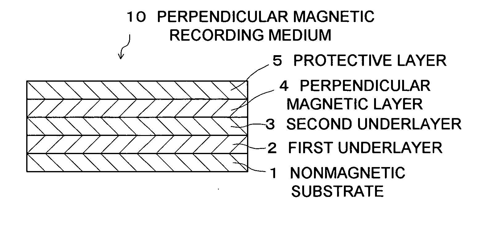
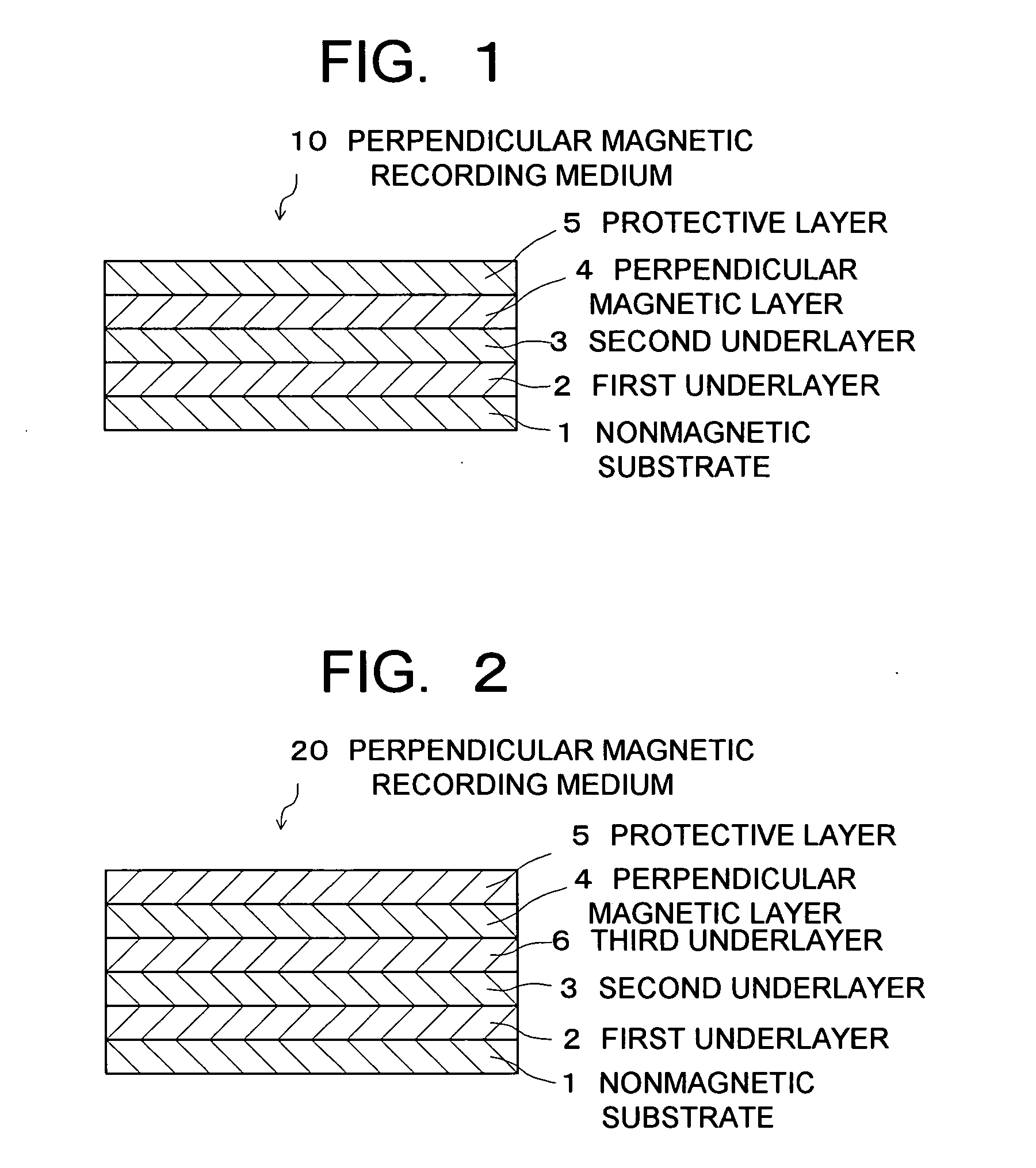
[0073] A nonmagnetic substrate made of crystallized glass for a 2.5-inch magnetic disk was prepared. This nonmagnetic substrate was placed in a vacuum chamber with a vacuum degree of 1×10⁻⁵ Pa, was heated to the temperature of 250° C., and was subjected to DC magnetron sputtering in an Ar atmosphere at a gas pressure of 0.6 Pa.

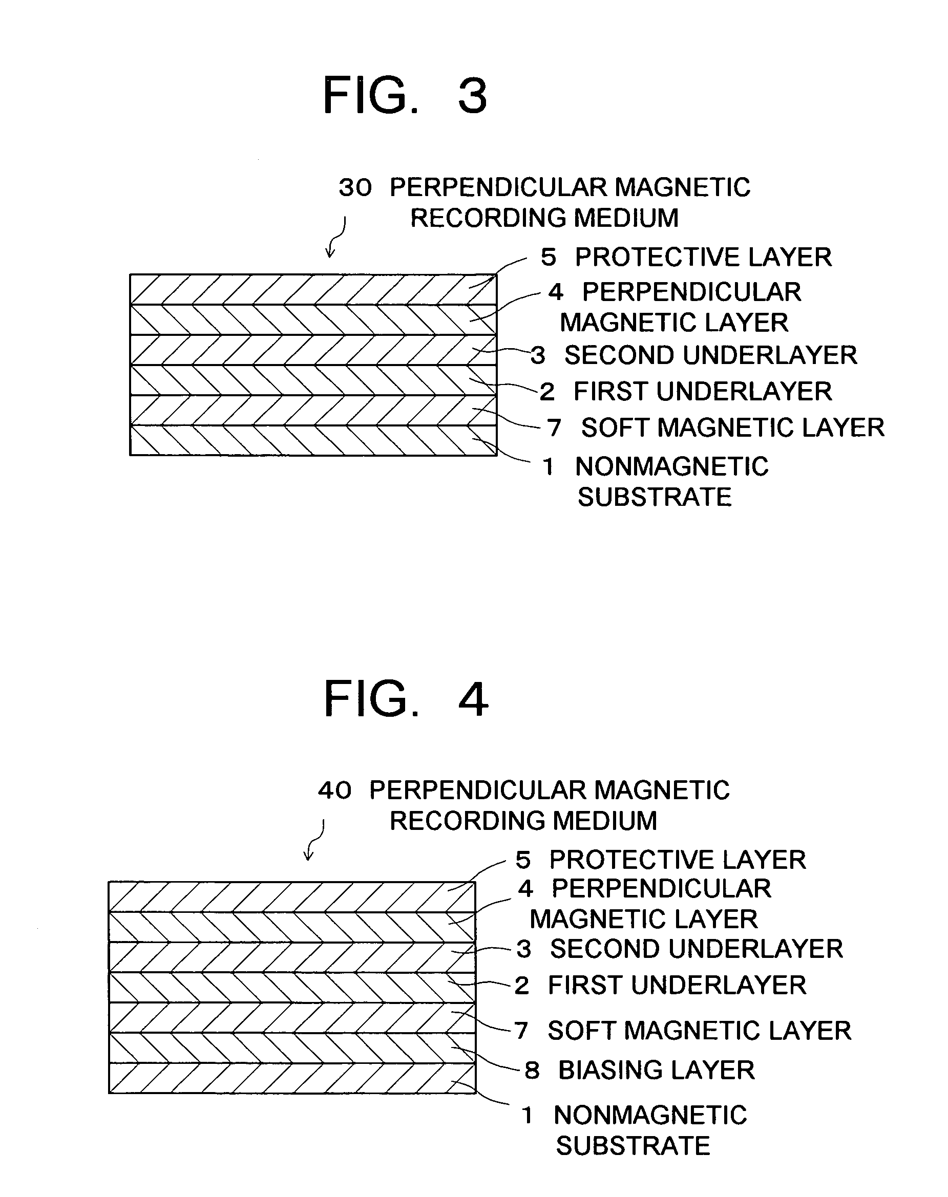
[0074] First, the nonmagnetic substrate was disposed to face a target, and DC500 W was discharged to the target, thereby forming a Cr layer to a thickness of 40 nm as a backing nonmagnetic layer. A CoCrPt ferromagnetic layer was formed thereon as a biasing layer to have a thickness of 25 nm. On the resultant CoCrPt ferromagnetic layer, a CoZrNb soft magnetic layer with a thickness of 200 nm was formed.

[0075] Thereafter, on the CoZrNb soft magnetic layer, a FeO-SiO2 layer as a first underlayer was formed to have a thickness of 10 nm by using a FeO-30 mol % SiO2 target and discharging 500 W.

[0076] Thereafter, the resultant workpiece was heated to 500° C. in a...

example 2

[0094] As the first underlayer 12, a CoO-30 mol % SiO2 composite target was prepared. A perpendicular magnetic recording medium was fabricated in the same manner as in the example 1 except that the above composite target was used instead of the FeO-30 mol % SiO2 composite target.

[0095] The resultant perpendicular magnetic recording medium has the same layer structure as that of the perpendicular magnetic recording medium 50 shown in FIG. 6 except that the first underlayer 12 is different.

[0096] TEM observation and image processing were conducted on the first underlayer 12 of the resultant perpendicular magnetic recording medium 50 in the same manner as in the example 1, and the grain size distribution of crystal grains of the first underlayer 12 was examined. The result showed that the first underlayer 12 was formed of crystal grains with a grain size of about 5 nm, and a standard deviation of the grain distribution was 0.8 nm or less. Further, grain boundaries with a thickness of...

example 3

[0105] As the first underlayer 12, MgO-40 mol % SiO2 composite targets were prepared. Perpendicular magnetic recording media were fabricated in the same manner as in the example 1 except that the MgO-40 mol % SiO2 composite targets were used instead of the FeO-30 mol % SiO2 composite target and film thickness was variously changed.

[0106] Each of the resultant perpendicular magnetic recording media has the same layer structure as that of the perpendicular magnetic recording medium 50 shown in FIG. 6 except that the first underlayer 12 is different.

[0107] On each of the various perpendicular magnetic recording media that were obtained, the grain size distribution was measured and a recording / reproducing characteristic was evaluated in the same manner as in the example 1.

[0108]FIG. 7 shows a graph representing the correlation between film thickness and SNRm and between film thickness and crystal grain size in the first underlayer of MgO-40 mol % SiO2. Curves 101, 111 are graphs repr...


PUM

PropertyMeasurementUnit
thicknessaaaaaaaaaa
thicknessaaaaaaaaaa
grain sizeaaaaaaaaaa

Abstract

Disclosed is a perpendicular magnetic recording medium including: a nonmagnetic substrate; a first underlayer formed on the nonmagnetic substrate, mainly composed of at least two kinds selected from a group consisting of Fe2O3, CO3O4, MgO, MoO3, Mn3O4, SiO2, Al2O3, TiO2, and ZrO2, and having crystal grains growing in a columnar shape and crystal grain boundaries surrounding the crystal grains; a nonmagnetic second underlayer formed on the first underlayer and having crystal grains with one of a face-centered cubic structure and a hexagonal close-packed structure growing on the crystal grains of the first underlayer; a magnetic layer formed on the second underlayer; and a protective film formed on the magnetic layer.

Description

CROSS REFERENCE TO RELATED APPLICATIONS [0001] This application is based upon and claims the benefit of priority from the prior Japanese Patent Application No. 2004-90673, filed on Mar. 25, 2004; the entire contents of which are incorporated herein by reference. BACKGROUND [0002] 1. Field of the Invention [0003] The present invention relates to a magnetic recording medium used for a hard disk device using a magnetic recording technology and to a magnetic recording / reproducing apparatus using the same. [0004] 2. Description of the Related Art [0005] A problem of increase in noise generated from a medium has arisen as recording density becomes higher in response to a demand for a larger capacity of a hard disk device. The noise from a medium is thought to be ascribable mainly to zigzag magnetic domain walls in bit boundaries. This is because various factors such as a writing magnetic field of a head and the size of grains constituting an internal part of the medium are involved in det...

Claims


Application Information

Patent Timeline
Patent Type & Authority Applications(United States)
IPC IPC(8): G11B5/64G11B5/738G11B5/65G11B5/66G11B5/667G11B5/73H01F10/16
CPCG11B5/7325G11B5/656G11B5/737
Inventor IWASAKI, TAKESHIKIKITSU, AKIRAOIKAWA, SOICHIMAEDA, TOMOYUKI
Owner KK TOSHIBA
Why Eureka
Try Eureka