Exhaust purifying apparatus and exhaust purifying method for internal combustion engine

a technology of exhaust purification apparatus and purification method, which is applied in mechanical equipment, electric control, machines/engines, etc., can solve the problems of erroneous determination, inability to end sulfur release control, and error in the determination of whether an abnormality has occurred in sulfur release control

Active Publication Date: 2005-10-06
TOYOTA JIDOSHA KK
View PDF5 Cites 15 Cited by
  • Summary
  • Abstract
  • Description
  • Claims
  • Application Information

AI Technical Summary

Benefits of technology

[0018] Accordingly, it is an objective of the present invention to provide an exhaust purifying apparatus for an internal combustion engine, the internal combustion engine, and an exhaust purifying method for an internal combustion engine that promptly and accurately determine the existence of an abnormality in sulfur release control, which causes an exhaust purifying catalyst to release sulfur.

Problems solved by technology

Therefore, the sulfur release control cannot be ended.
In a case where the existence of an abnormality is determined based on a parameter that is indirectly affected by the abnormality that has occurred in the sulfur release control, that is, based on only the actual time of the sulfur release control, if the predetermined time (TL0+TH0) is set to a relatively short time, there may be an error in the determination of whether an abnormality has occurred in the sulfur release control.
As a result, an erroneous determination may be made that the control has caused an abnormality.
However, if the predetermined time (TL0+TH0) is set longer, it takes time to make a determination as to when an abnormality actually occurs in the sulfur release control.
This delays measures to be taken in response to the abnormality based on the determination result.

Method used


Image

  • Exhaust purifying apparatus and exhaust purifying method for internal combustion engine
  • Exhaust purifying apparatus and exhaust purifying method for internal combustion engine
  • Exhaust purifying apparatus and exhaust purifying method for internal combustion engine

Examples


Embodiment Construction

[0030] An exhaust purifying apparatus for a vehicle diesel engine according to one embodiment of the present invention will be described with reference to the drawings.

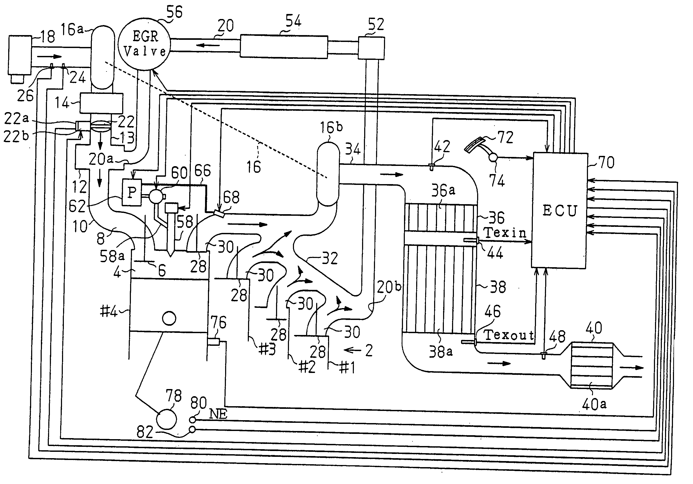
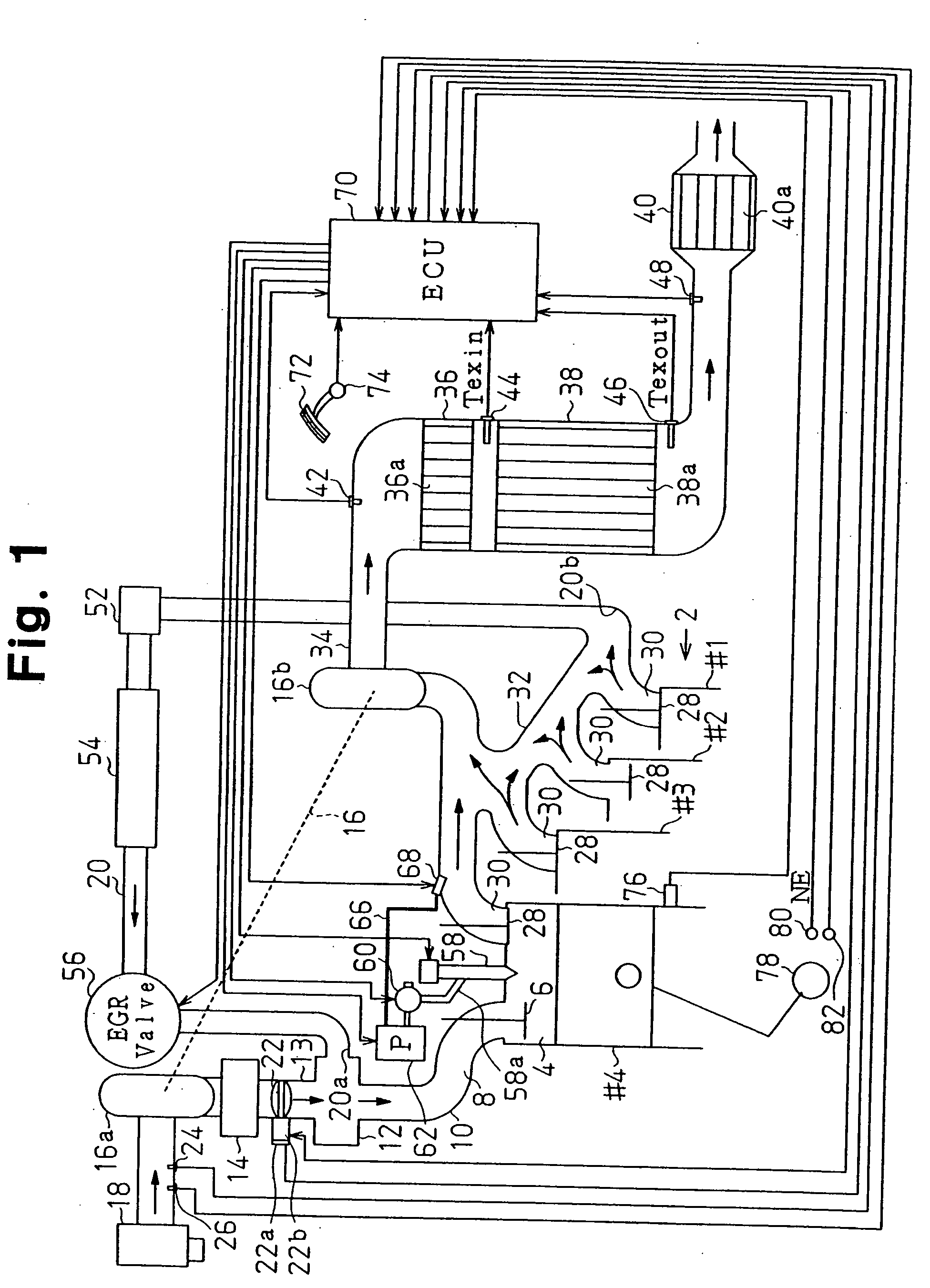
[0031] As shown in FIG. 1, the diesel engine 2 has cylinders. In this embodiment, the number of the cylinders is four, and the cylinders are denoted as #1, #2, #3, and #4. A combustion chamber 4 for each of the cylinders #1 to #4 includes an intake port 8, which is opened and closed by an intake valve 6. The combustion chambers 4 are connected to a surge tank 12 via the intake ports 8 and an intake manifold 10. The surge tank 12 is connected to an intercooler 14 and the outlet of a compressor 16a of an exhaust turbocharger 16 with an intake passage 13. The inlet of the compressor 16a is connected to an air cleaner 18. An exhaust gas recirculation passage 20 (hereinafter, referred to as EGR) is connected to the surge tank 12. Specifically, an EGR gas supply port 20a of the EGR passage 20 opens to the surge tank 12. A ...


PUM


Abstract

During sulfur release control in an internal combustion engine, a rich period and a lean period are alternately repeated. The air-fuel ratio of exhaust gas is controlled toward a target air-fuel ratio (14.3) by adding fuel from a fuel adding valve in the rich period. An ECU determines whether the actual air-fuel ratio of exhaust gas detected by an air-fuel ratio sensor has reached a stoichiometric air-fuel ratio each time the rich period ends at which addition of fuel from the fuel adding valve is stopped. A counter counts the number of times the ECU has determined that the actual air-fuel ratio of exhaust gas has not reached the stoichiometric air-fuel ratio. When the value of the counter becomes greater than or equal to a permissible value, the ECU determines that there is an abnormality in the sulfur release control.

Description

BACKGROUND OF THE INVENTION [0001] The present invention relates to an exhaust purifying apparatus and an exhaust purifying method for an internal combustion engine. [0002] An exhaust purifying catalyst for an internal combustion engine that performs lean combustion such as a diesel engine, particularly, a NOx storage-reduction catalyst is poisoned by sulfur components contained in fuel. If the level of poisoning is high, the NOx storage-reduction capacity of the NOx storage-reduction catalyst is decreased. Therefore, when the NOx storage-reduction catalyst is poisoned by the sulfur components to a certain level, that is, when the sulfur components have accumulated in the NOx storage-reduction catalyst by a certain amount, a sulfur release control is performed to release the sulfur components from the catalyst. In the sulfur release control, while maintaining the catalyst bed temperature high, the air-fuel ratio of exhaust gas detected by an air-fuel ratio sensor is subjected to fee...

Claims


Application Information

Patent Timeline
Patent Type & Authority Applications(United States)
IPC IPC(8): F01N3/035F01N3/08F02D45/00F01N3/20F01N3/24F01N13/02F02B37/00F02D41/02F02D41/14F02D41/22F02M25/07
CPCF01N3/035F01N13/0097F01N3/0821F01N3/0842F01N2250/02F01N2250/12F01N2250/14F01N2570/04F01N2570/10F01N2570/12F01N2570/14F02B37/00F02D41/028F02D41/22F02M25/0707F02M25/0727F02M25/074F02M25/0756F01N13/009F01N3/0814F02M26/48F02M26/05F02M26/23F02M26/35
Inventor UCHIDA, TAKAHIROSUGIYAMA, TATSUMASA
Owner TOYOTA JIDOSHA KK
Why Eureka
Try Eureka