System utilizing waste heat of internal combustion engine
- Summary
- Abstract
- Description
- Claims
- Application Information
AI Technical Summary
Benefits of technology
Problems solved by technology
Method used
Image

Examples
first embodiment
[0026] [First Embodiment]
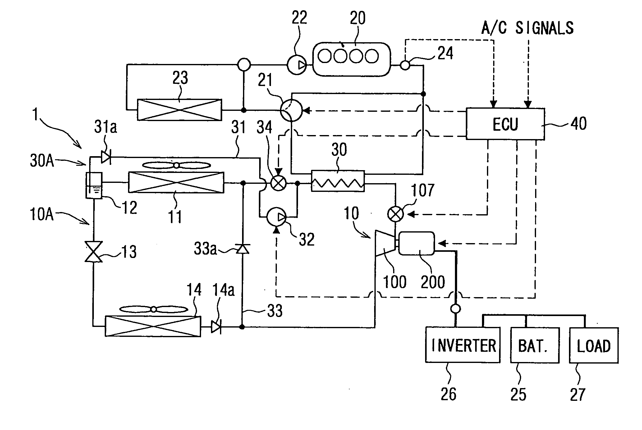
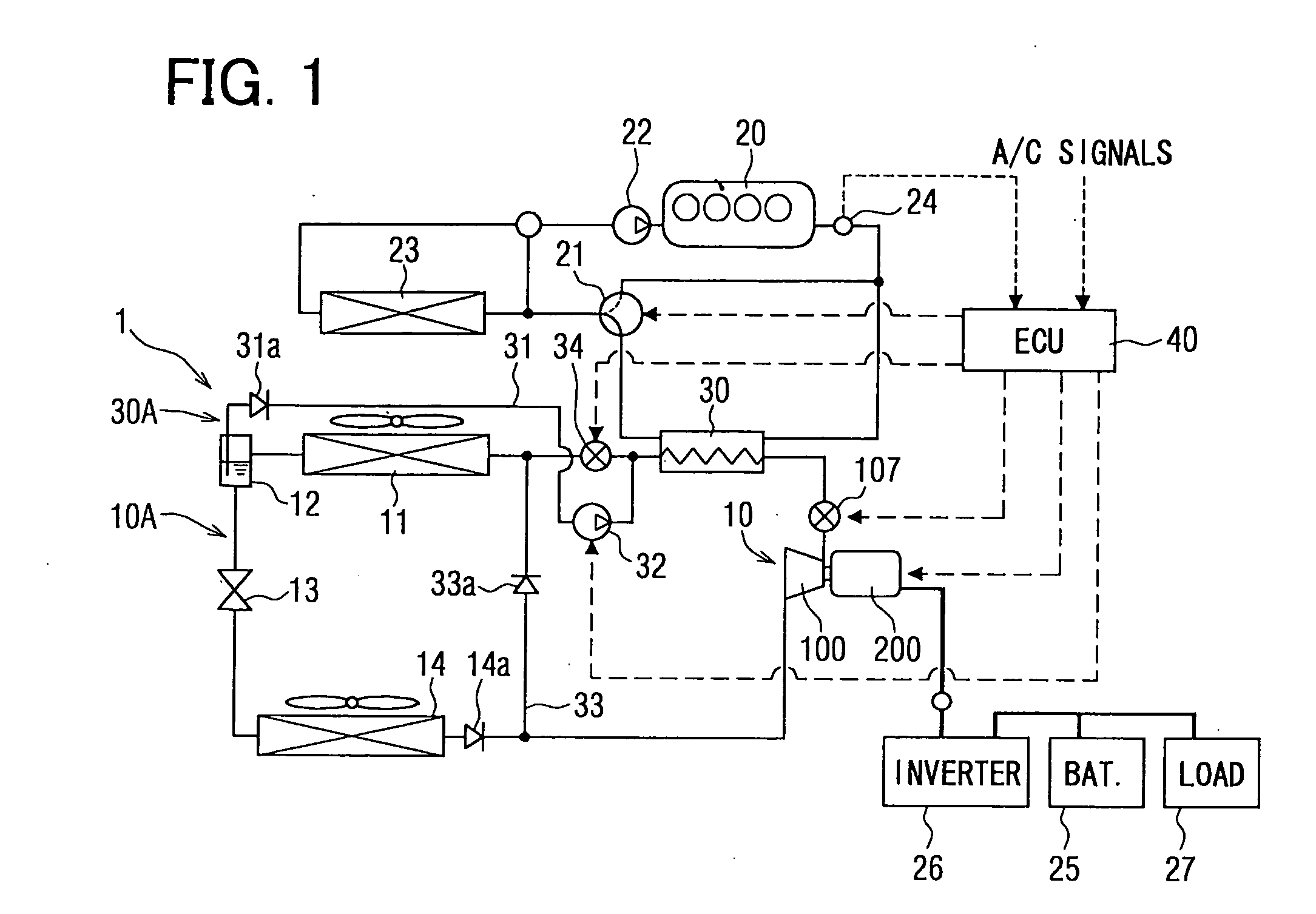
[0027] In a first embodiment, a system utilizing waste heat of an internal combustion engine is mounted on a hybrid vehicle or a vehicle with an engine which stops at idling. The system utilizing waste heat of the internal combustion engine is referred to as a waste heat utilizing system 1 hereinafter, and the internal combustion engine is referred to as an engine 20 hereinafter. The waste heat utilizing system 1 includes a refrigerant cycle 10A and a Rankine cycle 30A which recovers energy of waste heat generated in the engine 20. An electronic control unit 40, which is referred to as ECU 40 hereinafter, controls each of the cycles 10A, 20A. Referring to FIG. 1, a whole arrangement of the waste heat utilizing system 1 is described.
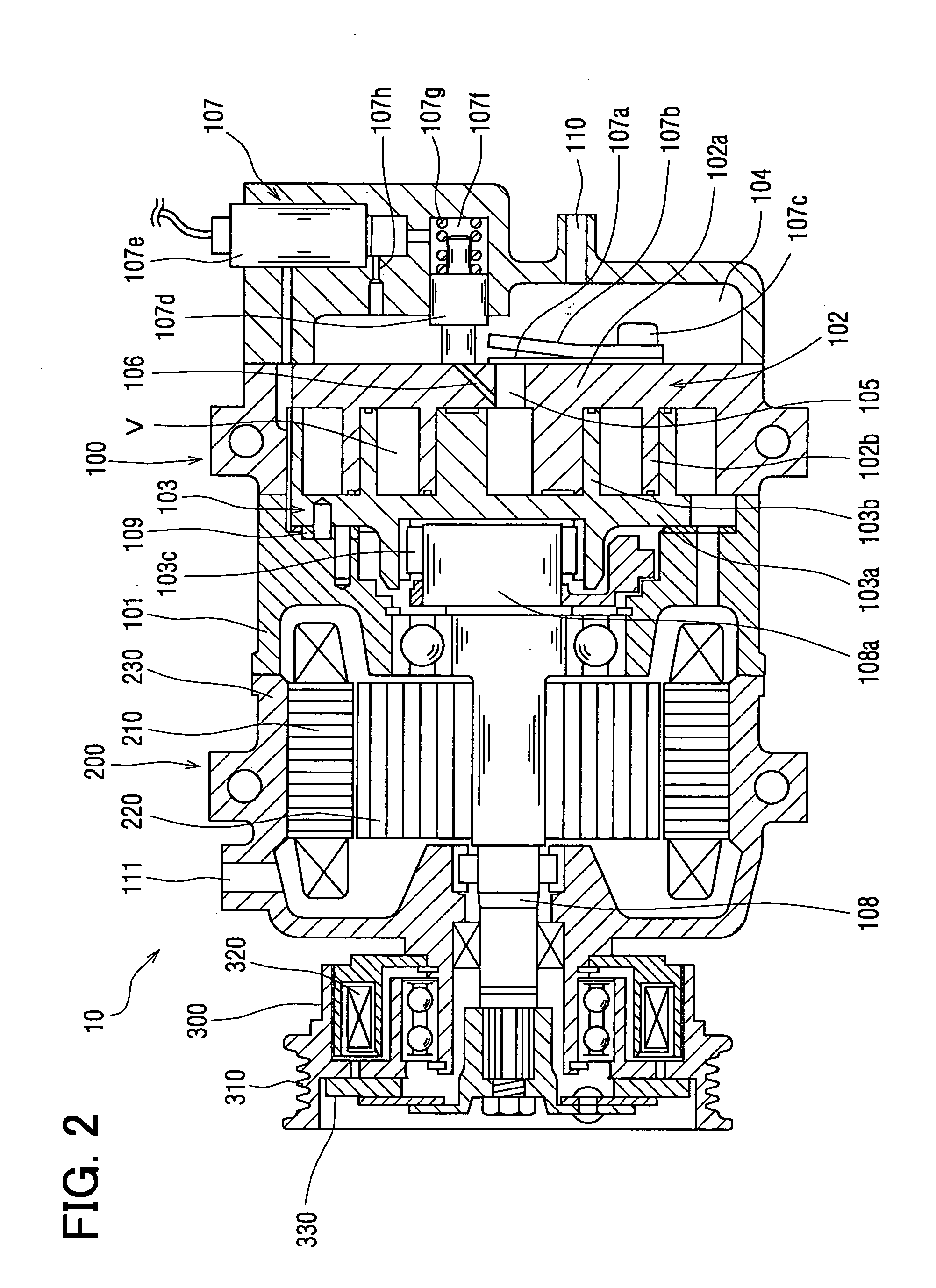
[0028] An expansion-compression device 10 is a fluid machine which operates in a pump-mode where gas-phase refrigerant is compressed and discharged, and in a motor-mode where an expanding fluid pressure of the super-heated gas-ph...
second embodiment
[0095] [Second Embodiment]
[0096] Referring to FIGS. 7 to 9, the second embodiment is described hereinafter. The difference between FIG. 5 and FIG. 7 is that step S415A in FIG. 5 is replaced by step S415B in FIG. 7.
[0097] That is, after the liquid pump 32 is stopped in step S405, it is determined whether the higher-side pressure of the refrigerant is decreased lower than the predetermined pressure P2 (a second predetermined pressure of the present invention) in step S415B. The second predetermined pressure P2 is a pressure in which no expansion is occurred in the pump-motor mechanism 100.
[0098] Alternatively, as indicated in step S415C in FIG. 8, it can be determined whether the pressure difference between the higher-side pressure and the lower-side pressure of the liquid pump 32 is decreased lower than a predetermined pressure difference ΔP.
[0099] When the predetermine pressure P2 is used in step S415B, the predetermined pressure P2 is not always precise in the case that the high...
third embodiment
[0101] [Third Embodiment]
[0102]FIG. 10 illustrates the third embodiment, in which the expansion-compression device 10 is altered comparing with the first and second embodiments.
[0103] The expansion-compression device 10 has a variable speed mechanism 400 including a planetary gear mechanism which can switch a power transmitting route and increase / decrease the speed of the rotation.
[0104] The variable speed mechanism 400 has a sun gear 401 at the center thereof, a pinion gear 402a, a planetary carrier 402, and a ring gear 403.
[0105] The sun gear 401 is integrated with the rotor 220 of the rotational electric machine 200. The planetary carrier 402 is integrated with the shaft 331 which rotates with the friction plate 330 of the electromagnetic clutch 300. The ring gear 403 is integrated with the shaft 108.
[0106] A one-way clutch 500 is disposed between the shaft 331 and the stator housing 230. The one-way clutch 500 allows the rotational of the shaft 331 in one direction, which co...
PUM
 Abstract
Description
Claims
Application Information
 - R&D
- Intellectual Property
- Life Sciences
- Materials
- Tech Scout
- Unparalleled Data Quality
- Higher Quality Content
- 60% Fewer Hallucinations
Browse by: Latest US Patents, China's latest patents, Technical Efficacy Thesaurus, Application Domain, Technology Topic, Popular Technical Reports.
© 2025 PatSnap. All rights reserved.Legal|Privacy policy|Modern Slavery Act Transparency Statement|Sitemap|About US| Contact US: help@patsnap.com