Glow ring ignition assist for internal combustion engine

Inactive Publication Date: 2005-10-06
WESTPORT POWER
View PDF13 Cites 15 Cited by
  • Summary
  • Abstract
  • Description
  • Claims
  • Application Information

AI Technical Summary

Benefits of technology

[0011] The present disclosure introduces a glow member within the combustion chamber that assists in ignition of gaseous fuel and other fuels with a relatively high auto-ignition temperature, compared to diesel fuel. The glow member either ini

Problems solved by technology

As such, conditions within the cylinder may not provide the necessary environment for auto-ignition when the same environment can auto-ignite diesel.
One of the problems with this method is that the glow plug is a point source of heat within the combustion chamber.
Therefore, it takes time for

Method used


Image

  • Glow ring ignition assist for internal combustion engine
  • Glow ring ignition assist for internal combustion engine
  • Glow ring ignition assist for internal combustion engine

Examples


first embodiment

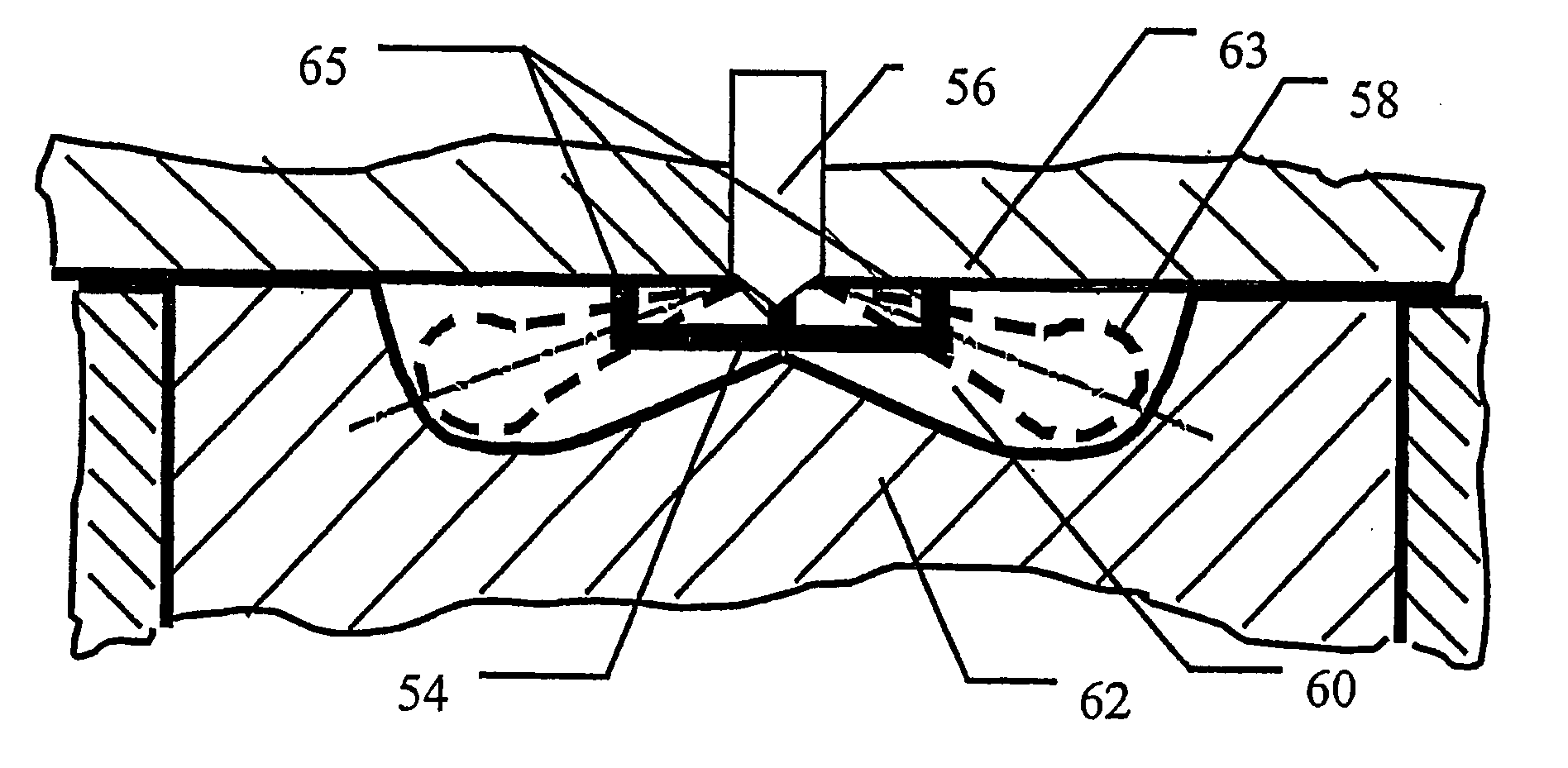
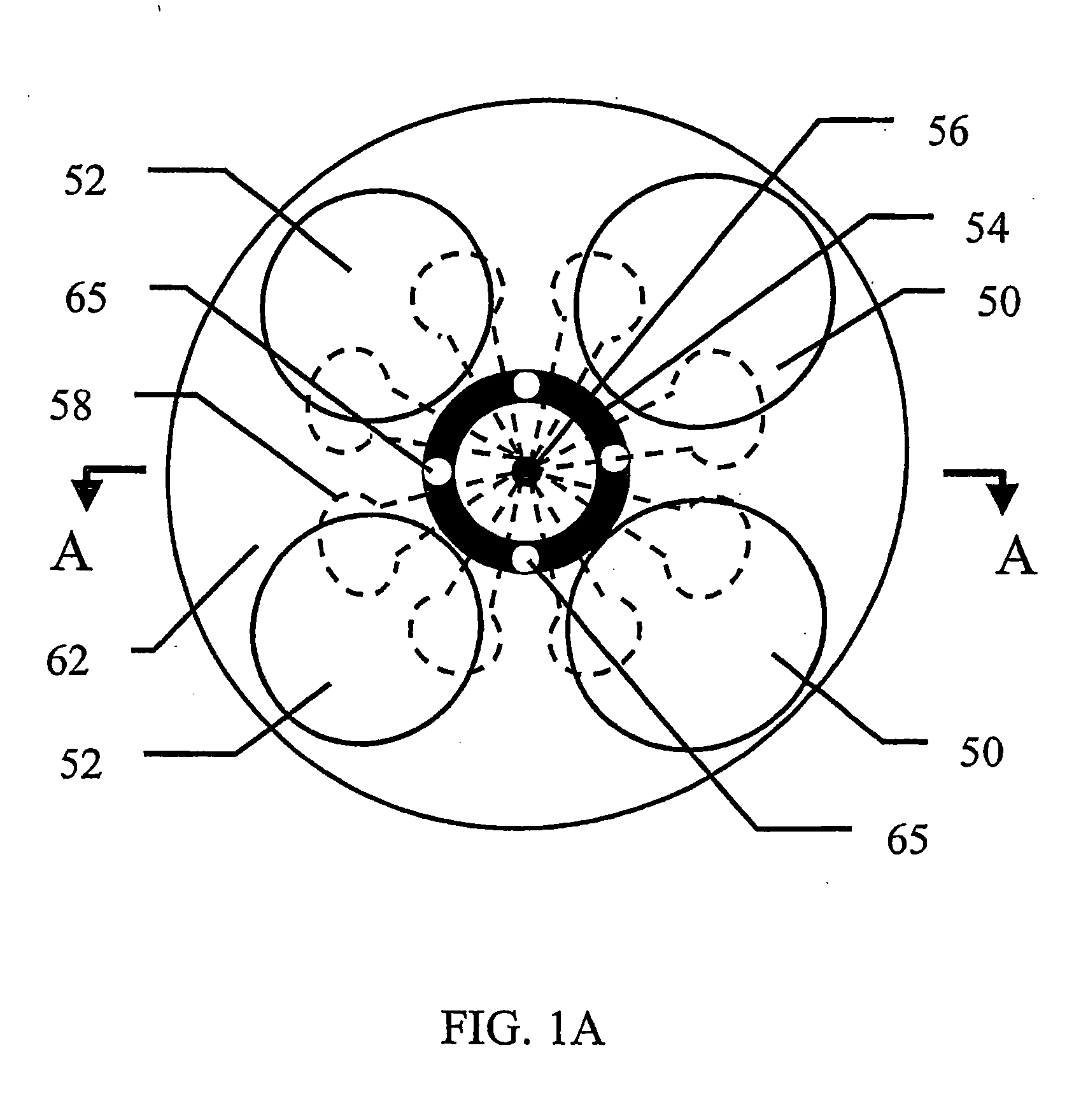
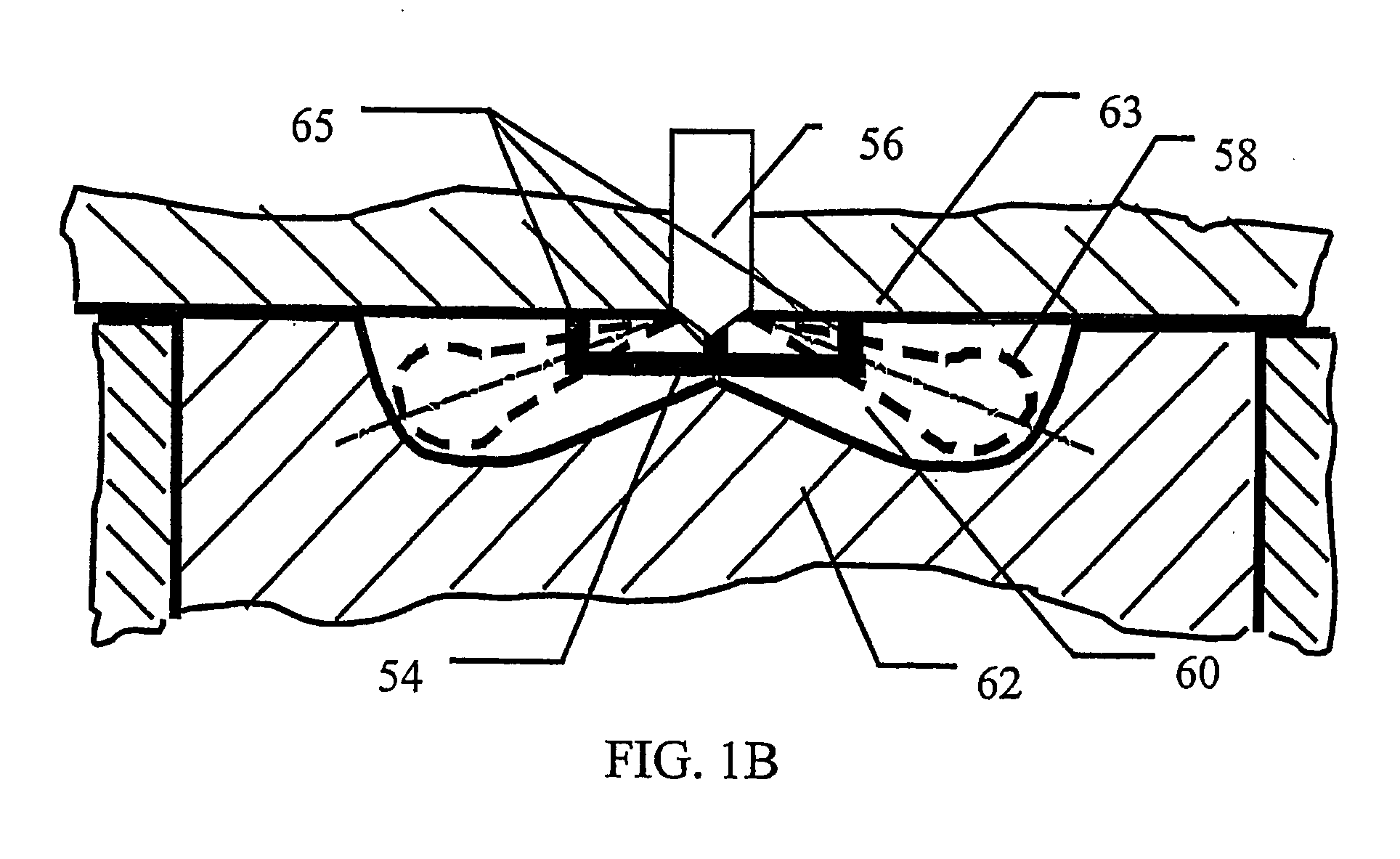
[0040] the subject disclosure is shown with intake valves 50 and exhaust valves 52 outlined in the top view. Glow member 54, and the nozzle of fuel injection valve 56 are disposed within combustion chamber 60. Dashed lines outline the general shape of fuel jets 58. In FIG. 1b, piston 62 is at or near top dead center within combustion chamber 60. The side view of FIG. 1b also shows fire deck 63 along with posts 65, from which glow member 54 is supported.

[0041] Note that fuel jets 58 are shown demonstrating a typical spray pattern within the combustion chamber. FIGS. 1a and 1b show how fuel jets 58 can be directed to the proximity of glow member 54 so that at least a portion of the fuel in fuel jets 58 is heatable by the glow member to assist with igniting the fuel.

[0042] Referring to FIG. 1b, glow member 54 is shown affixed to fire deck 63. Glow member 54 is provided in this first embodiment at a distance from fire deck 63 and with a circumference that provides a hot surface area, w...

second embodiment

[0057] Referring to FIGS. 2a and 2b, a second embodiment is provided. In this embodiment, passive glow member 92 is affixed to piston 90 by posts 93. Again fuel jet 94 is outlined being injected into combustion chamber 96, which is partially defined by piston 90. FIG. 2a shows the location of intake valves 98 and exhaust valves 100. While the illustrated embodiment employs a four-valve arrangement (two intake valves and two exhaust valves), glow member 92 can be employed with a different number of intake or exhaust valves. Also shown by the illustrated embodiment is a combustion chamber with centrally positioned fuel injection valve 102 from which fuel jets 94 originate.

[0058] The second embodiment works in generally the same way as the first embodiment. However, as this second embodiment shows the glow member attached to piston 90 instead of fire deck 105, glow member 92 will only come into direct contact with fuel jets 58 when the piston is at or near top dead center. Therefore, i...

third embodiment

[0060] Referring to FIG. 3, a third embodiment is provided wherein an active glow member is shown. Glow member 200 is attached to support member 202, which is, in turn, attached to injection valve sleeve 204. Fuel injection valve 206 is shown mounted inside injection valve sleeve 204. Injection valve nozzle orifices 208 are shown with fuel jets 210. Fuel eddies 212 are shown generated near and beyond support member 202 which acts as a barrier in the path of at least a portion of the fuel jet. Positive and negative power leads 214 and 216 are shown as well. Fire deck 218 defines one boundary of the combustion chamber from which protrudes injection valve 206.

[0061] In this preferred embodiment of actively heated glow member 200, support member 202 is attached to an end of injection valve sleeve 204 that extends below fire deck 218 and that projects into the combustion chamber. Glow member 200 is attached to support member 202 as shown, and support member 202 also projects into the com...


PUM


Abstract

A glow member, preferably in the shape of a ring, assists ignition and combustion of a fuel used in an internal combustion engine. A fuel injection valve injects a plurality of fuel jets directly into a combustion chamber during operation of the engine so that the fuel jets are aimed to the proximity of the glow member such that ignition of fuel in each fuel jet is assisted by the glow member. The glow member is made from high temperature materials and can include catalytic materials to further promote combustion. The glow member can be actively heated, for example by an electric current, in addition to being passively heated by the heat generated within the combustion chamber by the combustion of the fuel therein.

Description

CROSS-REFERENCE TO RELATED APPLICATION(S) [0001] This application is a continuation of International Application No. PCT / CA2003 / 001437, having an international filing date of Oct. 2, 2003, entitled “Glow Ring Ignition Assist for Internal Combustion Engine”. International Application No. PCT / CA2003 / 001437 claimed priority benefits, in turn, from Canadian Patent Application No. 2,406,297 filed Oct. 2, 2002. International Application No. PCT / CA2003 / 001437 is also hereby incorporated by reference herein in its entirety.FIELD OF THE INVENTION [0002] The present disclosure relates to an apparatus for assisting ignition and combustion of a fuel used to drive an internal combustion engine. BACKGROUND OF THE INVENTION [0003] Fuel alternatives to diesel, including gaseous fuels such as natural gas, hydrogen, ethane, and blends of such gaseous fuels, when used to power internal combustion engines, can significantly reduce emissions of pollutants when compared to the same engines fuelled by die...

Claims


Application Information

Patent Timeline
IPC IPC(8): F02B3/06F02B9/06F02B23/06F02B43/04F02D41/00F02D41/40F02M21/02F02M57/00F02M61/18F02P19/00F02P19/02
CPCF02B3/06Y02T10/36F02B23/0651F02B23/0654F02B23/0669F02B23/0696F02B43/04F02B2023/0606F02B2275/14F02D41/0027F02D41/402F02M57/00F02M61/1806F02P19/00F02P19/02Y02T10/125Y02T10/123Y02T10/32F02M21/0215F02M21/0275F02M21/029F02B23/0621Y02T10/12Y02T10/30F02M21/02
Inventor HILL, PHILLIP G.LI, GUOWEIWEICH, ALAN B.DUNN, MARK E.ZHANG, DEHONG
Owner WESTPORT POWER
Why Eureka
Try Eureka