

Liquid crystal display device and manufacturing method thereof
- Summary
- Abstract
- Description
- Claims
- Application Information
AI Technical Summary
Benefits of technology
Problems solved by technology
Method used
Image

Examples
experiment example 1
Example 1
[0130] Nematic liquid crystal (BL006; made by Merck Ltd., anisotropy of refractive index: 0.286, anisotropy of dielectric constant: 17.3, viscosity: 71 mP·s, NI point: 113° C.)(60 parts), a chiral agent (CB15; made by Merck Ltd.)(38 parts) and a gelling agent (2 parts) represented by the aforementioned chemical formula (2) were mixed to prepare a chiral nematic liquid crystal composition.
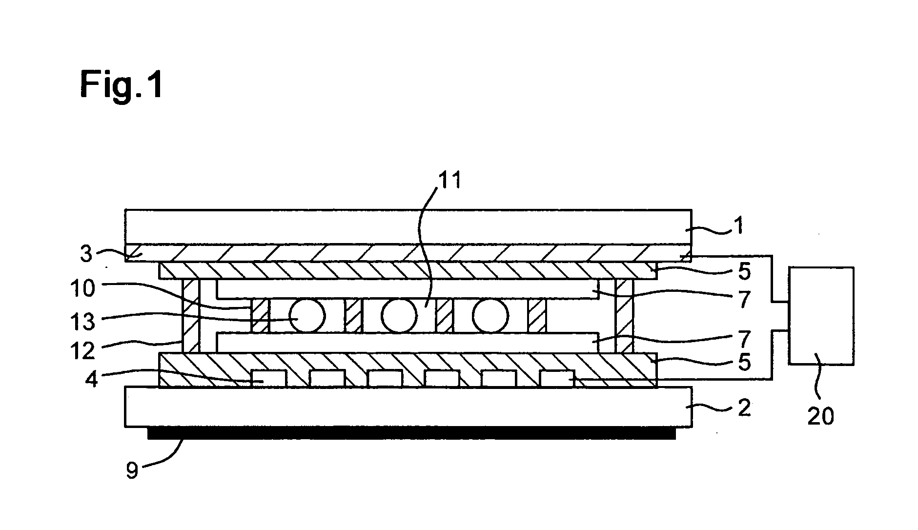
[0131] By using the resulting liquid crystal composition and materials described below, a display device as shown in FIG. 1 (in which polymer structures and an insulating thin film were not shown) was manufactured. The cell gap was 5.5 μm. The respective values were measured at 25° C. [0132] Substrate: Glass 0.7 mm [0133] ITO sheet resistance value: 10 Ω / □[0134] Orientation film: Soluble polyimide (Perpendicular orientation film AL-2022; made by JSR Corporation) [0135] Thickness of orientation film: 60 nm (printed) [0136] Spacer: Micropearl 5.5 μm; made by Sekisui Fine Chemical Co., Ltd. ...
example 2
[0139] The same method as example 1 was used except that the amount of addition of the gelling agent was changed to 3 parts to prepare a display device.
[0140] The resulting display device was subjected to UV irradiation, and variations in the Y value (FC) and the whiteness degree parameter (PL) in response to the irradiation time were traced (UV luminance: 5 mW / cm2). With respect to the respective irradiation times, spectral distribution curves in the respective PL state and FC state in the display device were measured. The results of the measurements are respectively shown in FIGS. 7(A) and 7(B). Here, in FIG. 7(B), the spectral distribution curves of the PL state and FC state in the respective irradiation times are respectively superposed on one curve.
experiment example 2
Wavelength Dependence
[0156] The same method as example 1 was used, except that the mixed ratio of BL006 (made by Merck Ltd.) and CB15 (made by Merck Ltd.) in the chiral nematic liquid crystal composition was changed so that the peak wavelength of selective reflection in the spectral distribution curve of the resulting display device was set to a predetermined value and that the cell gap was changed to 7.0 μm, to manufacture a plurality of display devices having different peak wavelengths of selective reflection.
[0157] The Y value (PL) and Y value (FC) of the resulting display device were measured to examine the relationship between the peak wavelength of selective reflection and the Y value. With respect to display devices having respective peak wavelengths of selective reflection of 350 nm, 580 nm and 800 nm, spectral distribution curves were measured. FIGS. 9(A) to 9(C) show the results of the measurements.
[0158]FIG. 9(A) shows that when the peak wavelength of selective reflect...
PUM
| Property | Measurement | Unit |
|---|---|---|
| Percent by mass | aaaaa | aaaaa |
| Percent by mass | aaaaa | aaaaa |
| Wavelength | aaaaa | aaaaa |
Abstract
Description
Claims
Application Information