Multistage optical amplifier having tilt compensation feature

a multi-stage optical amplifier and tilt compensation technology, applied in the field of optical amplifiers, can solve the problems of reducing the transmission and reducing the transmission quality of a wideband wdm transmission system. , the effect of reducing the transmission quality

Inactive Publication Date: 2005-10-06
FUJITSU LTD
View PDF14 Cites 4 Cited by
  • Summary
  • Abstract
  • Description
  • Claims
  • Application Information

AI Technical Summary

Benefits of technology

[0022] According to the present invention, degradation of transmission quality due to accumulated tilt can be inhibited collectively without using expensive modules such as optical demultiplexers and optical multiplexers and, therefore, the transmission quality in a wideband WDM transmission system can be improved in an appropriate device size and at a reasonable cost.
[0023] Further, according to the present invention, the tilt cancellation control and gain control of the former-stage amplifier and the latter-stage amplifier is performed by the common control section. Therefore, by combining said tilt cancellation control wit

Problems solved by technology

However, as the OSNR of the channels, the level of which is reduced due to the tilt described above, is reduced significantly, the transmission distance, the number of transmission spans or the number of multiplexed wavelengths (or, in other words, the transmission bandwidth) will be restricted.
However, in the device configuration using optical demultiplexers and optical multiplexers every several spans for level adjustment of separate channels as in the conventional example, there is a problem in that the size and cost of the device is increased.
In this case, as optical amplifiers are typically required to compensate for insertion losses generated when the channel signals pass through the optical demultiplexers and optical multiplexers, there is also a problem in that amplified spontaneous emi

Method used


Image

  • Multistage optical amplifier having tilt compensation feature
  • Multistage optical amplifier having tilt compensation feature
  • Multistage optical amplifier having tilt compensation feature

Examples


first embodiment

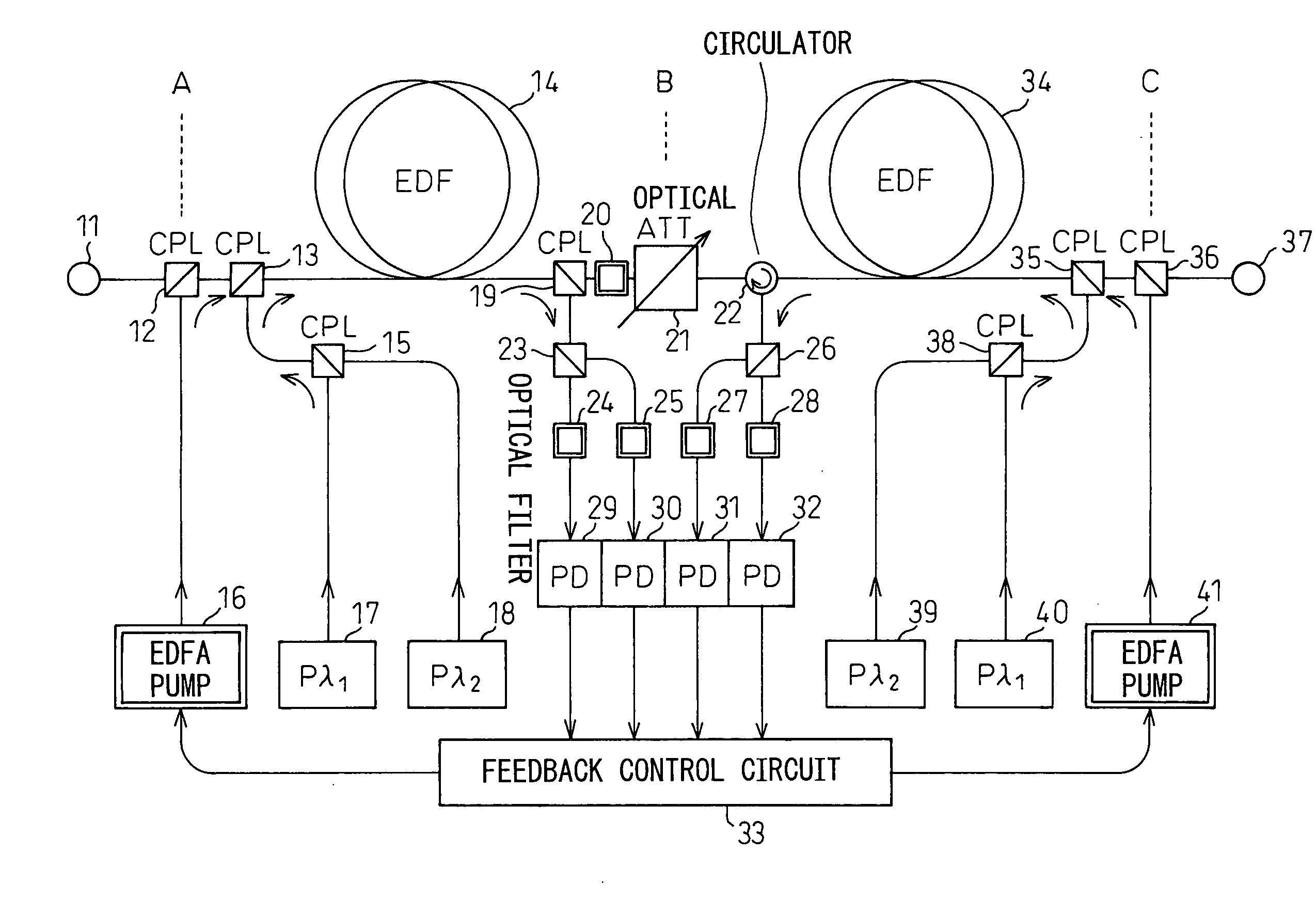
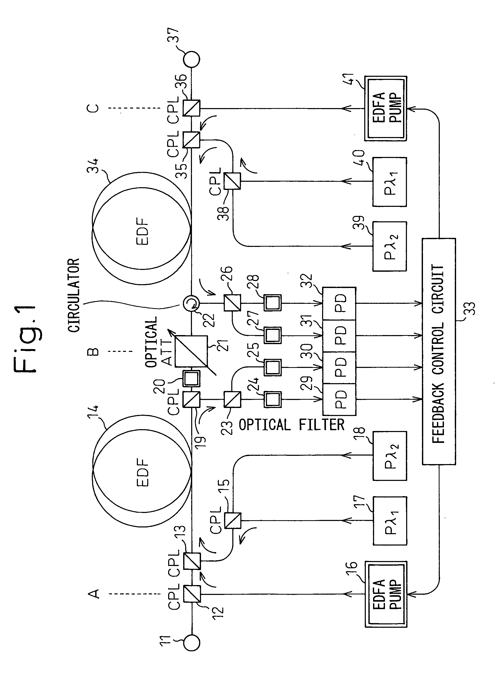
[0044]FIG. 1 shows a multistage optical amplifier having a tilt compensation feature according to the present invention. Though a two-stage optical amplifier is exemplified in this example, the present invention is not limited to such a configuration.

[0045] In FIG. 1, a main signal is input from an input port 11 and, in an optical coupler (CPL) 12, coupled with a pumping light from an EDFA pumping section (EDFA Pump) 16 for the former stage. The signal is further coupled with two probe lights Pλ1 and Pλ2 from probe light sources 17 and 18, respectively, for the former stage via optical couplers (CPL) 15 and 13 and, then, input to an erbium doped fiber (EDF) 14 for the former stage.

[0046] The EDF 14 amplifies the input main signal and probe lights by the pumping light and a portion of the amplified signal is separated by an optical coupler (CPL) 19. The portion of the signal separated by the optical coupler 19 is further divided into two waves in a subsequent optical coupler (CPL) 2...

second embodiment

[0070]FIG. 6 shows a multistage optical amplifier having a tilt compensation feature according to the present invention. Though a two-stage optical amplifier is exemplified also here, the present invention is not limited to such configuration.

[0071] In FIG. 6, a Raman fiber amplifier (RAMAN) 61 is adopted as an optical amplifier in the latter stage and, therefore, a Raman fiber pumping section (RAMAN Pump) 62 is provided. Other configuration is similar to that in FIG. 1.

[0072] In general, the EDFA can achieve flat gain characteristics only in a relatively narrow bandwidth and the range of the available pumping light power in such bandwidth is restricted. On the other hand, in the Raman fiber amplifier that amplifies signals via stimulated Raman scattering in optical fibers, gain bandwidth is not restricted unlike in the EDFA and, further, arbitrary gain characteristics can be achieved to some extent by using a plurality of pumping light powers. However, in the Raman fiber amplifier...

third embodiment

[0093]FIG. 12 shows a multistage optical amplifier having a tilt compensation feature according to the present invention. Though a two-stage optical amplifier is exemplified also in this example, the present invention is not limited to such configuration.

[0094] In FIG. 12, the multistage optical amplifier is provided with two latter-stage Raman fiber pumping sections 63 and 64 that can be controlled independently by the feedback control section 33 and utilizes a well-known four-wave mixed light generated by pumping lights λ1′ and λ2′ from the Raman fiber pumping sections 63 and 64 so that the pumping light for the former-stage EDF 14 can also be generated. This eliminates the need for the former-stage EDFA pumping section 16 and the optical coupler 12 for coupling the pumping light from the EDFA pumping section 16 to the transmission path of the main signal and, therefore, these elements are omitted in FIG. 12. On the other hand, an optical coupler 65 is provided for multiplexing th...


PUM


Abstract

The present invention relates to an optical amplifier and, in particular, it relates to multistage optical amplification having a feature for compensating for the tilt that is generated when a signal having a plurality of optical wavelengths and the like according to a wavelength division multiplexing (WDM) method is amplified in a wide bandwidth. The multistage optical amplifier comprises: a plurality of optical amplifiers that are connected in a multistage manner; and a common control section for commonly controlling pumping light powers of said plurality of optical amplifiers, wherein said common control section includes: tilt detection means for detecting amounts of tilt of each of said plurality of optical amplifiers; and tilt cancellation means for controlling the pumping light powers of said plurality of optical amplifiers so that the amounts of tilt of each of the optical amplifiers detected by said tilt detection means cancel each other.

Description

BACKGROUND OF THE INVENTION [0001] 1. Field of the Invention [0002] The present invention relates to an optical amplifier and, in particular, it relates to a multistage optical amplifier that amplifies a signal having a plurality of optical wavelengths (hereinafter referred to as a “main signal” or a “channel”), and the like, in the wide bandwidth used in a WDM (wavelength Division Multiplexing) system. [0003] 2. Description of the Related Art [0004] In recent years, as the Internet has rapidly become widespread, an optical wavelength division multiplexing transmission technique that enables large-capacity and long-distance transmission has attracted attention. In the optical amplification used for the long-distance WDM transmission system, an erbium doped fiber amplifier (EDFA), in which erbium is doped into optical fiber cores, is used. Further, as the number of wavelengths is increased due to the increase of speed and capacity of communications, a Raman fiber amplifier that has a...

Claims


Application Information

Patent Timeline
IPC IPC(8): G02F1/35G02F1/365H01S3/00H01S3/067H01S3/10H01S3/13H01S3/16H01S3/30H04B10/07H04B10/29H04B10/294H04J14/00H04J14/02
CPCH01S3/005H01S3/06758H01S3/10007H01S3/10015H04B2210/003H01S3/1608H01S2301/04H04B10/2941H01S3/1305H01S3/13013
Inventor NATORI, HIDEZUMISEKIYA, MOTOYOSHIFUJITA, TAKEHIRO
Owner FUJITSU LTD
Why Eureka
Try Eureka