Adaptation of a vehicle stabilizing system to the surface

a vehicle stabilizing system and surface technology, applied in the field of vehicle stabilizing systems, can solve problems such as undesirable stabilizing interventions, and achieve the effects of avoiding incorrect settings, reducing the influence of vehicle stabilization, and ensuring stability

Active Publication Date: 2005-10-06
SYMANTEC CORP +1
View PDF9 Cites 25 Cited by
  • Summary
  • Abstract
  • Description
  • Claims
  • Application Information

AI Technical Summary

Benefits of technology

[0017] According to a preferred embodiment of the present invention, a change in the control response is allowed only if the vehicle stabilizing system (VSS) is not active. This in particular prevents the control response from being changed in an already critical driving situation and negatively influencing the vehicle stabilization.
[0018] Moreover, a controller variable is preferably not changed abruptly but gradually. To this end, a “fadeover” function, for example, may be provided via which the controller variable is guided to the new value of the controller variable. This fadeover function calculates, for example, a plurality of intermediate values based on an interpolation principle, the intermediate values being considered in succession. As a result, the regulation operates substantially more smoothly.
[0019] If the VSS reports a fault condition which arose, for example, due to a sensor error or a transient undervoltage, the change in a controller variable is preferably also not allowed and the corresponding algorithm is preferably switched to a safe mode (e.g., the standard mode). This measure in turn contributes to an avoidance of incorrect settings and accordingly to an increase in driving safety.

Problems solved by technology

However in off-road driving in particular, such as climbing in a streambed or driving in deep sand, the vehicle behaves entirely differently than when driving on asphalt, so that even in non-critical driving situations, stabilizing interventions may occur which are not desirable under the special conditions.

Method used


Image

  • Adaptation of a vehicle stabilizing system to the surface
  • Adaptation of a vehicle stabilizing system to the surface

Examples


Embodiment Construction

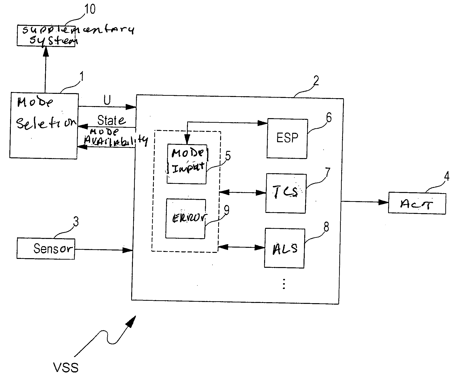
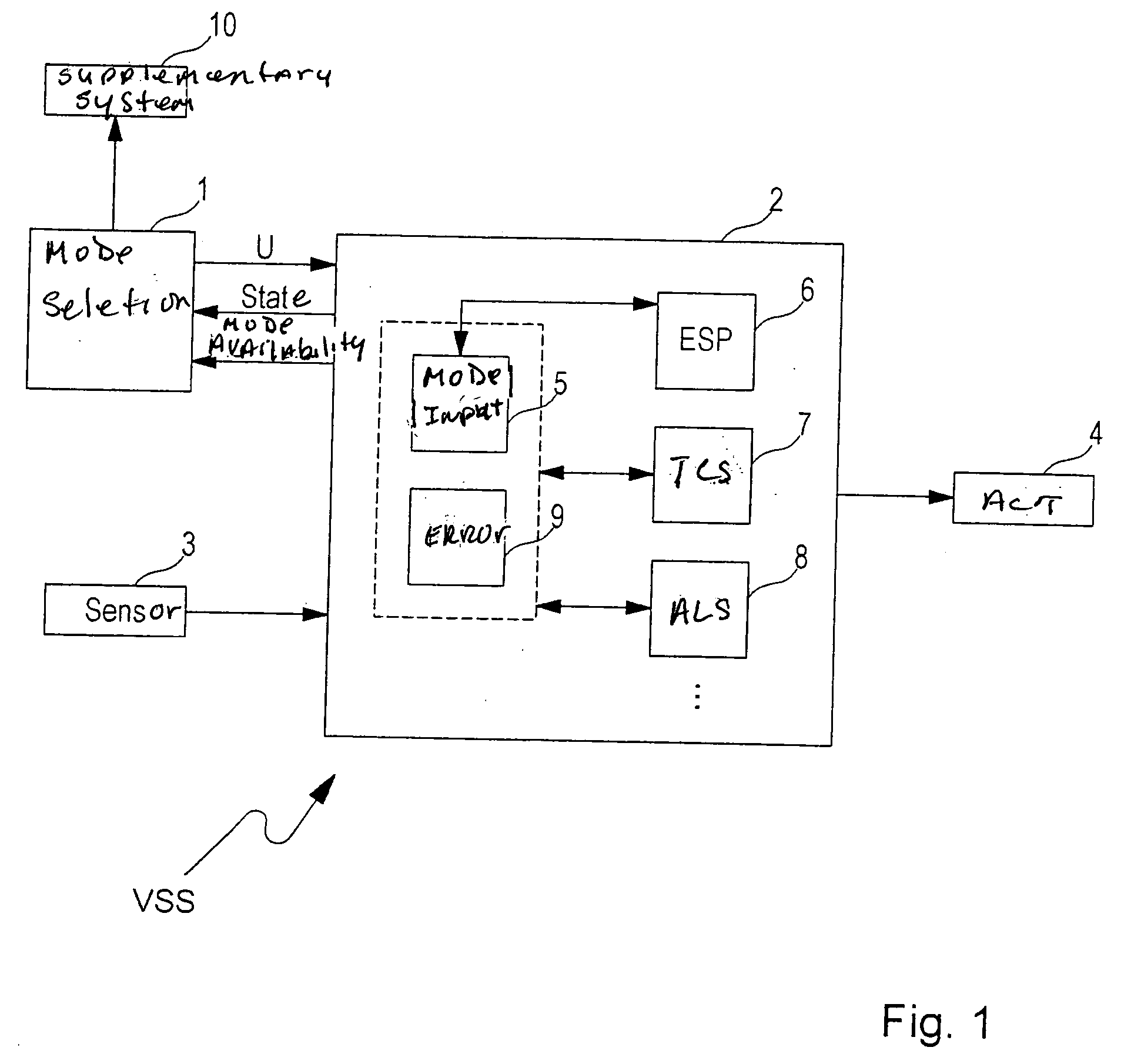
[0028] As shown in FIG. 1, vehicle stabilizing system VSS essentially includes a control unit 2 in which various stabilization control algorithms 6, 7, 8 are stored, a sensor system 3 for detecting present actual values of driving state variables (e.g., wheel speeds, steering wheel angle, braking pressure, yaw rate, etc.), and various actuators 4 such as wheel brakes, an engine control unit, etc. for implementing a stabilizing intervention when an unstable driving situation is detected. For the sake of clarity, the sensors and actuators of system VSS are each combined in a block 3 and 4, respectively.

[0029] Stabilizing system VSS here includes control algorithms ESP 6, TCS 7, and ALS 8, each of which may include one or a plurality of control functions. Algorithm ESP 6 may contain, for example, a rollover mitigation (ROM), a steering angle control (e.g., AFS), or another known supplemental control function which is based, for example, on a yaw rate control. In addition to aforementi...


PUM


Abstract

A vehicle stabilizing system, for motor vehicles in particular, includes a control unit in which a stabilization control algorithm is stored, a sensor system for detecting present actual values of vehicle state variables, and at least one actuator for implementing a stabilizing intervention when an unstable situation is detected. In order to be able to adapt the vehicle stabilizing system to different types of surfaces, a device is provided which supplies the control unit with information concerning the nature of the surface and at least one controller variable of the stabilization control algorithm is changed as a function of the supplied surface information.

Description

FIELD OF THE INVENTION [0001] The present invention relates to a vehicle stabilizing system, for motor vehicles in particular, and a method for vehicle stabilization. BACKGROUND INFORMATION [0002] Vehicle stabilizing systems (VSS) primarily include the anti-lock system (ALS), traction control system (TCS), or electronic stability program (ESP) and are used to improve the controllability of motor vehicles in critical driving situations, e.g., for oversteering when negotiating turns, and to stabilize the vehicle. In addition to the named systems, the term “vehicle stabilizing system” is also understood to include stabilizing functions such as, for example, active front steering (AFS), other vehicle stabilizing systems such as active spring-and-shock-absorber systems (vertical force distribution systems), the known supplemental functions of ESP such as, for example, the rollover mitigation (ROM) function, active cruise control (ACC), and principally all regulating systems that may inte...

Claims


Application Information

Patent Timeline
Patent Type & Authority Applications(United States)
IPC IPC(8): B60G17/00B60G21/10B60K28/16B60K31/00B60T8/00B60T8/1755B60W10/18B60W10/20B62D6/00B62D37/00G06F7/00
CPCB60T8/1755B60T2210/12B60T2210/16B60W10/18B60W10/20B62D6/007B60G17/00B60G17/0165B60T8/00
Inventor ERBAN, ANDREASKIEREN, MARTINSCHUMANN, ANDREASRECKEFUSS, ALEXANDERTORRALBO, ANTONIO MALLOLREINER, CHRISTIAN
Owner SYMANTEC CORP
Why Eureka
Try Eureka