Vehicle cabin heating system with wax motor three-way valve

a technology of three-way valves and wax motors, which is applied in the direction of valve housings, engine starters, machines/engines, etc., can solve the problems of wax motors, achieve the effects of reducing the number of valves

Inactive Publication Date: 2005-10-13
PARKER HANNIFIN CORP
View PDF24 Cites 16 Cited by
  • Summary
  • Abstract
  • Description
  • Claims
  • Application Information

AI Technical Summary

Benefits of technology

[0007] The wax motor provides high force without the drawbacks associated with the more conventional vacuum actuated motor used in automotive applications. In addition, both the application and the release of the wax motor is not instantaneous, but rather, smooth and gentle. Wax motors may also be controlled by triacs without the need for snubber circuits because the wax motor is a resistive load rather than an inductive load. Moreover, a wax motor may survive situations where the plunger is blocked from full travel.
[0008] Other aspects of the invention relate to the valve assembly construction. More particularly, the valve assembly may include a two-piece valve body forming a stepped bore that simplifies molding of the valve body while providing a larger flow area for a smaller stroke of a valve shuttle. The valve assembly additionally or alternatively may include a conforming sealing member that enables low tolerance valve components to behave like tight tolerance components, thereby reducing manufacturing costs. The valve assembly further may be provided with a low current switching circuit for controlling a high current heater circuit.

Problems solved by technology

Moreover, a wax motor may survive situations where the plunger is blocked from full travel.

Method used


Image

  • Vehicle cabin heating system with wax motor three-way valve
  • Vehicle cabin heating system with wax motor three-way valve
  • Vehicle cabin heating system with wax motor three-way valve

Examples


Embodiment Construction

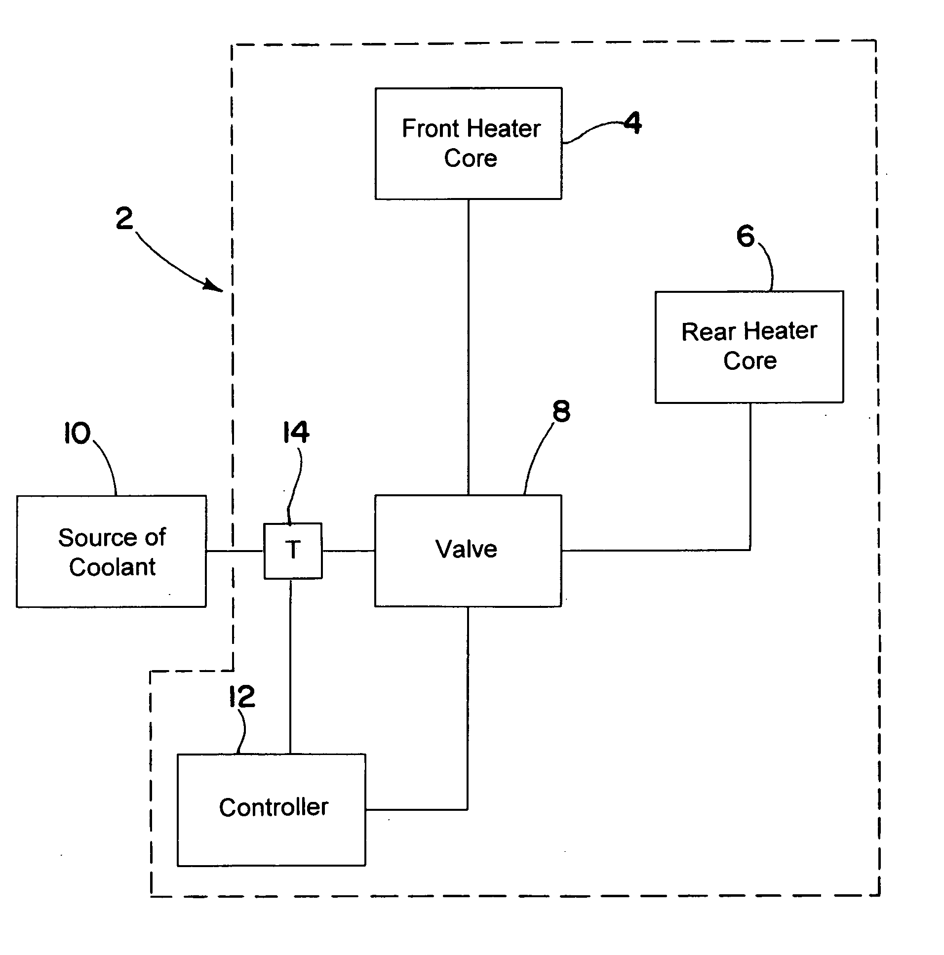
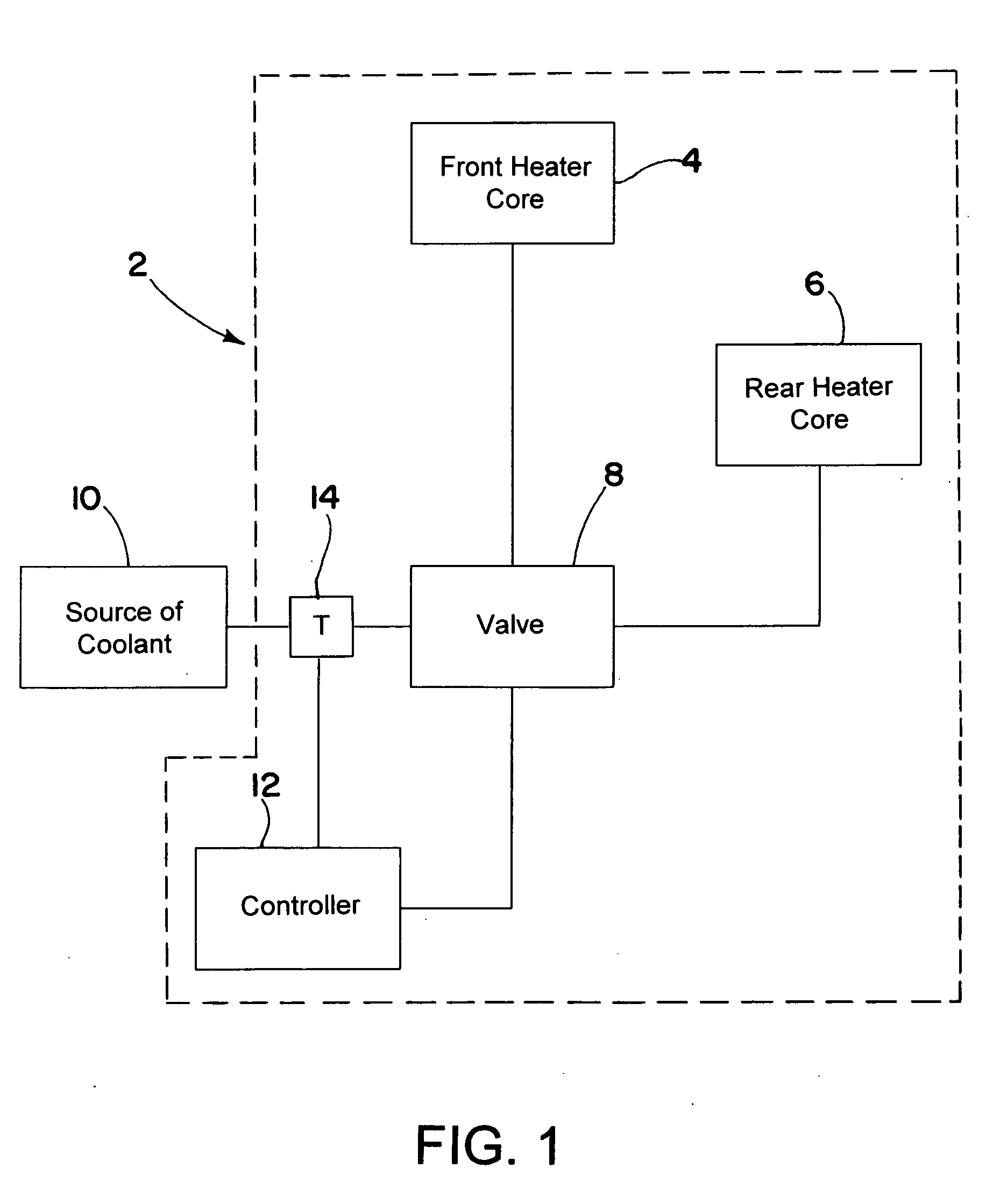
[0020] Referring now to the drawings in detail, and initially to FIG. 1, an exemplary vehicle heating system 2 in accordance with the invention generally comprises at least one heater core and a valve for controlling flow of coolant to the heater core. In the illustrated embodiment particularly suited for use in an sport utility vehicle (SUV) or other vehicle have a large interior cabin, there are two heater cores, a front heater core 4 and a rear heater core 6. The heater cores are connected by the valve 8 to a source of coolant, such as the engine coolant system 10 of the vehicle that extracts waste heat from the engine. The valve 8 is controlled by a controller 12 which modulates the valve 8 between open and closed positions in response to the temperature of the coolant that is sensed by a temperature sensor 14. In the illustrated embodiment and as is discussed further below, the valve 8 is configured to allow or shut off flow to the rear heater core 6 while continuously permitti...


PUM


Abstract

The present invention provides a wax motor actuated valve assembly for controlling the flow of coolant to a heater core or cores until the coolant reaches a predetermined operating temperature. The wax motor actuated valve has particular application to vehicle cabin heating systems comprising front and rear heat exchangers (cores) over which air can pass for heating front and rear portions of the cabin, respectively. Initially, flow to the rear heat exchanger is shut off until the temperature of the coolant reaches a predetermined elevated temperature, whereby initial coolant flow is directed to the front heat exchanger for more rapid heating of the forward portion of the vehicle cabin. After the predetermined elevated temperature has been reached, the wax motor valve assembly is actuated to supply coolant to the rear heat exchanger for heating the rear portion of the vehicle cabin.

Description

RELATED APPLICATIONS [0001] This application claims the benefit of U.S. Provisional Application No. 60 / 561,693 filed Apr. 13, 2004, which is hereby incorporated herein by reference.FIELD OF THE INVENTION [0002] The present invention relates generally to vehicle cabin heating systems and particularly those employing front and rear heat exchangers. The invention also relates to a valve having particular application in such heating system and more particularly to a wax motor actuated valve having a stepped bore. BACKGROUND OF THE INVENTION [0003] Motor vehicles generally include heating units to heat the interior of the vehicle (i.e., the cabin). In many automotive applications, a single heat exchanger, also known as a heater core, is located in the front of the vehicle beneath the dashboard. The heater core is normally connected to the water jacket of the vehicle's engine through a coolant circuit. When engine coolant passes through the water jacket, heat is transferred from the engin...

Claims


Application Information

Patent Timeline
Patent Type & Authority Applications(United States)
IPC IPC(8): F02N19/02F16K27/02F16K31/02
CPCF16K27/0263F16K31/025
Inventor KNIGHT, STEVEN R.MAXWELL, MARTIN C.
Owner PARKER HANNIFIN CORP
Why Eureka
Try Eureka