Switching power supply apparatus

a technology of switching power supply and power supply circuit, which is applied in the direction of electric variable regulation, process and machine control, instruments, etc., can solve the problems of ripple voltage, low frequency distortion, and easy design of each switching power supply circuit, and achieve the effect of low cos

Inactive Publication Date: 2005-10-13
TAMURA KK
View PDF2 Cites 17 Cited by
  • Summary
  • Abstract
  • Description
  • Claims
  • Application Information

AI Technical Summary

Benefits of technology

[0026] Therefore, it becomes possible to control the first and second switch elements synchronously.
[0027] According to the present invention, a synchronizing signal, which is required in driving a plurality of switching power supply circuits, is firmly transferred with insulation between the circuits, even if an applied switching frequency is high. Further, the switching power supply apparatus according to the present invention is small and low cost. Therefore, it can be applied for extensive applications.

Problems solved by technology

For example, when a common input voltage is applied to a plurality of switching power supply circuits, each of which having an independent drive circuit that controls a switch element, design of each switching power supply circuit becomes effortless.
However, a ripple voltage, such as low frequency distortion as a result of interference, is observed at the output in response to a switching frequency of each drive circuit.
Even if switching frequencies are the same among the plurality of switching power supply circuits, the following disadvantage may appear when drive signals for switching are not synchronized among the plurality of switching power supply circuits.
That is, in turning on / off a switch element of each switching power supply circuit, noise appears because of unmatched timing for the switching operations, which results in malfunction of the drive circuits and / or instability of control functions.
Furthermore, when the plurality of switching power supply circuits are not isolated electrically, for example, when they are connected to a common ground potential, or when a synchronizing signal is transferred without insulation, noise accompanied by on / off operation of a switch element of one switching power supply circuit may influence the other switching power supply circuit.
However, synchronous circuits for transferring a synchronizing signal with insulation suffer from the following disadvantages when photo-couplers are applied.
First, photo-couplers have limitation in high speed operation.
Accordingly, a driver for driving a photo-coupler with high speed may be required as a pre-circuit of the photo-coupler, which leads to increase of power dissipation (consumption) and cost.
Therefore, photo-couplers operable in reality are limited.
Second, even when photo-couplers operable with high frequency are procurable, a power supply device for a light detecting circuit (5V power supply device for example) may be further required, which leads to complexity of a circuit design and cost increase.
Third, large current is required for a photo-coupler in order to transfer a synchronizing signal with high speed.
Then, noise may occur in a synchronous circuit in response to timing of the drive current.

Method used


Image

  • Switching power supply apparatus
  • Switching power supply apparatus
  • Switching power supply apparatus

Examples


first embodiment

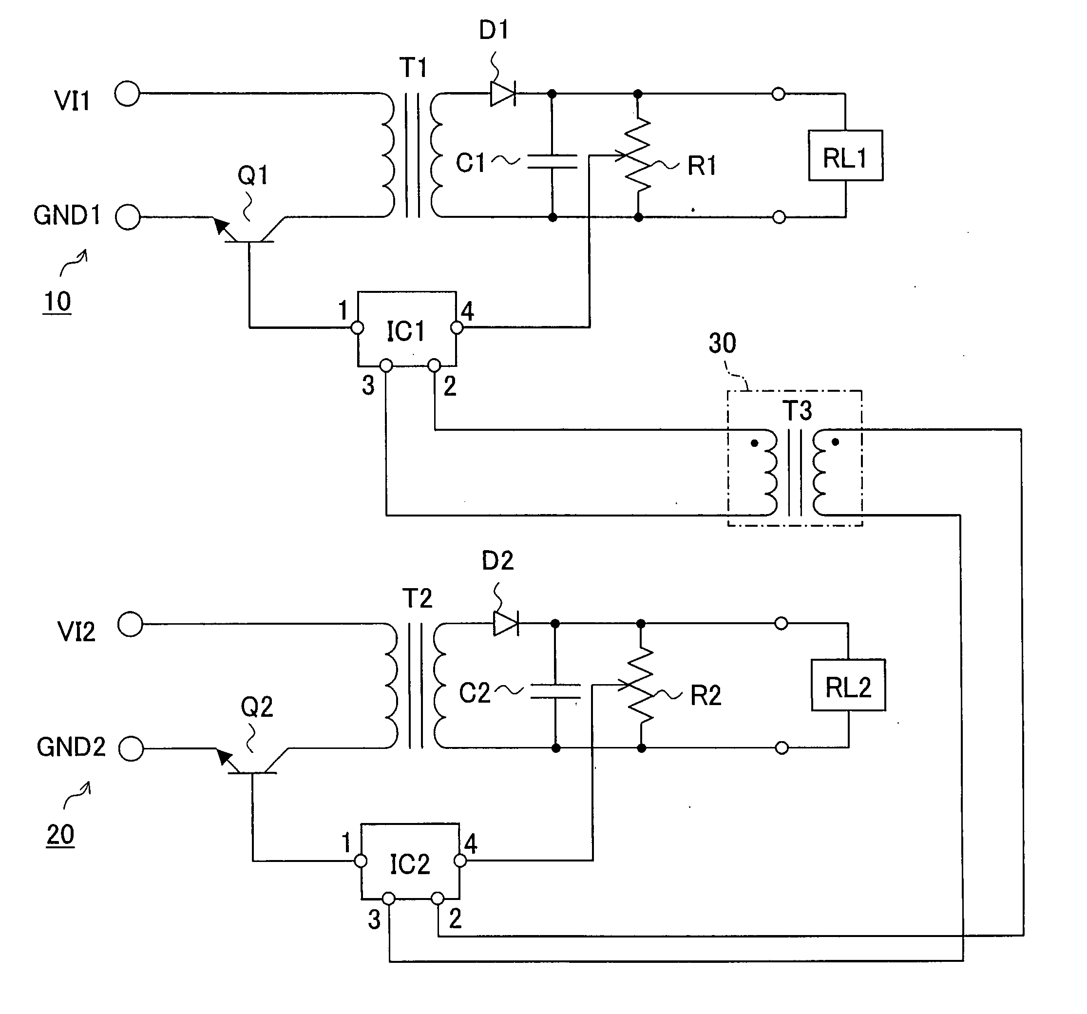
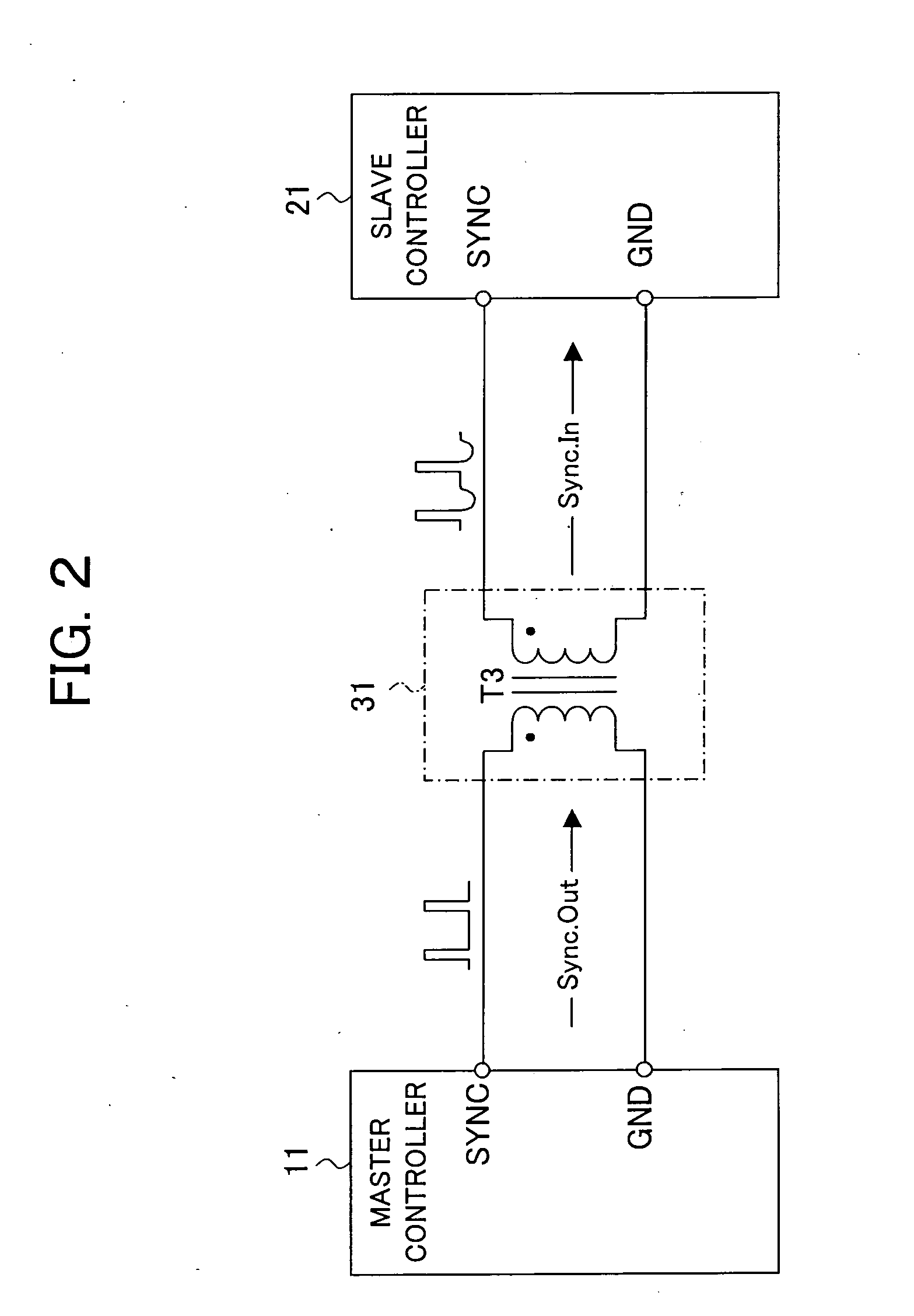
[0036]FIG. 1 shows an example of a circuit diagram of a switching power supply apparatus according to a first embodiment of the present invention.

[0037] In order to perform a synchronous operation among a plurality of switching power supply circuits that input a DC voltage independently, the switching power supply apparatus has a synchronous circuit for transferring a synchronizing signal among control ICs in the switching power supply circuits. The synchronizing signal is transferred with insulation, thereby reducing noise accompanied by the switching operation.

[0038] A constitution of the switching power supply apparatus shown in FIG. 1 will be described below.

[0039] As shown in FIG. 1, a switching power supply circuit 10 has a transistor Q1 (first switch element), a control IC1 (first controlling unit), a diode D1, a capacitor C1, and a resistor R1. Its output terminal is connected to a proper load RL1. A switching power supply circuit 20 has a transistor Q2 (second switch ele...

second embodiment

[0060] Next, a synchronous circuit of switching apparatus according to the second embodiment will be described.

[0061] The synchronous circuit of the switching apparatus according to the present embodiment generalizes the synchronous circuit according to the first embodiment. That is, the synchronous circuit 30 according to the first embodiment may be applicable almost all switching power supply apparatuses that control switching by control ICs, irrespective of the constitution of the above switching power supply circuits 10, 20.

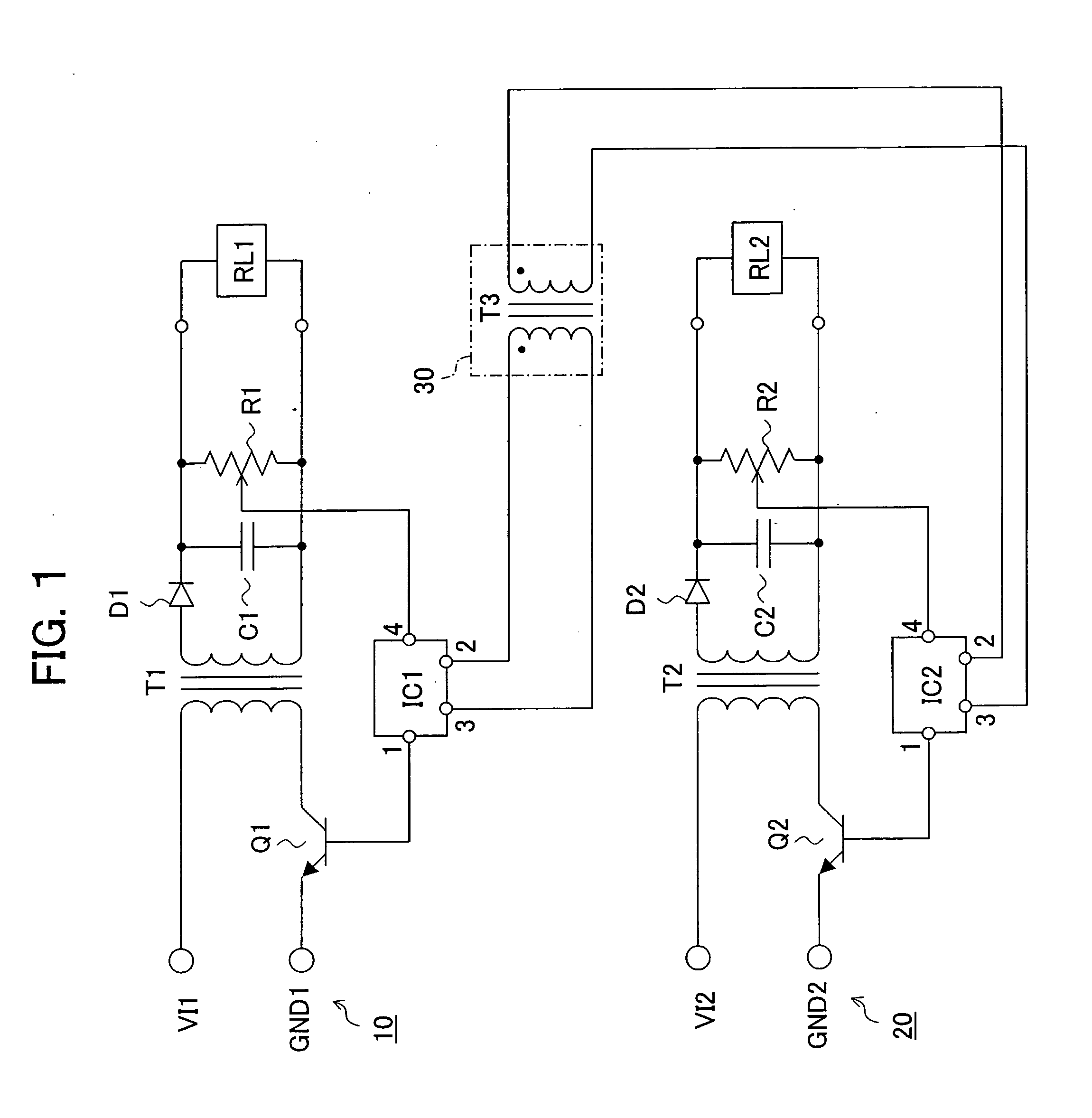
[0062]FIG. 2 is a circuit diagram of a synchronous circuit according to a second embodiment of the present invention.

[0063] In FIG. 2, a master controller (MASTER CONTROLLER) 11 and a slave controller (SLAVE CONTROLLER) 21 correspond to the control IC1 and the control IC2 respectively in the first embodiment. They control drive signals for switching. Namely, each controller sends out a signal (drive signal), which is used for controlling timing of switchin...

third embodiment

[0068] Next, an application example will be the described of synchronous circuit of switching apparatus according to the second embodiment.

[0069] In the second embodiment, the case was described in which a synchronizing signal transferred between the master controller 11 and the slave controller 21 was a clock pulse, with reference to FIG. 2. However, in reality, there is the case in which synchronization systems are different in controllers, and accordingly synchronizing signals applicable to the controllers are different.

[0070] A synchronous circuit of switching apparatus according to the present embodiment differs from the above synchronous circuit of switching apparatus in the second embodiment, in that a signal converter is added to adapt a difference of synchronizing signals of controllers.

[0071]FIG. 3 shows waveforms of synchronizing signals transferring between a master controller and a slave controller in which: (a) shows a clock synchronization system; (b) shows a ramp ...


PUM


Abstract

A switching power supply apparatus has a plurality of switching power supply circuits. A control IC (IC1) in a switching power supply circuit generates a PWM drive signal and a synchronizing signal, and also generates DC voltage according to a duty ratio of the PWM drive signal. A control IC (IC2) in the other switching power supply circuit is provided with the synchronizing signal from the IC1 via a transformer, and controls based on a PWM drive signal synchronized with the synchronizing signal. Therefore, switching timing completely matches among the plurality of switching power supply circuits.

Description

CROSS REFERENCES TO RELATED APPLICATIONS [0001] The present invention contains subject matter related to Japanese Patent Application No. JP 2004-99460 filed in the Japanese Patent Office on Mar. 30, 2004, the entire contents of which being incorporated herein by reference. BACKGROUND OF THE INVENTION [0002] 1. Field of the Invention [0003] The present invention relates to a switching power supply apparatus performing a switching control synchronously among a plurality of switching power supply circuits. [0004] 2. Description of the Related Art [0005] When driving a plurality of switching power supply circuits with different frequencies for each switching power supply circuit, the different frequencies causes beat and waviness that appear at an output. [0006] For example, when a common input voltage is applied to a plurality of switching power supply circuits, each of which having an independent drive circuit that controls a switch element, design of each switching power supply circu...

Claims


Application Information

Patent Timeline
Patent Type & Authority Applications(United States)
IPC IPC(8): H02M3/28H02J7/00H02M3/335
CPCH02M1/44H02M3/33507H02M3/33561Y10T307/852
Inventor SHAO, GELIANGOBIKATA, KIYOSHIYOSHIMI, KIMIOMATSUZAWA, KAZUNORIKUBOTA, MASARU
Owner TAMURA KK
Why Eureka
Try Eureka