

Thermally conductive compositions and methods of making thereof
a composition and conductive technology, applied in the field of thermally conductive compositions, can solve the problems of mechanical stress, loss of performance and failure of electronic components, and general existence of air gaps between surfaces
- Summary
- Abstract
- Description
- Claims
- Application Information
AI Technical Summary
Problems solved by technology
Method used
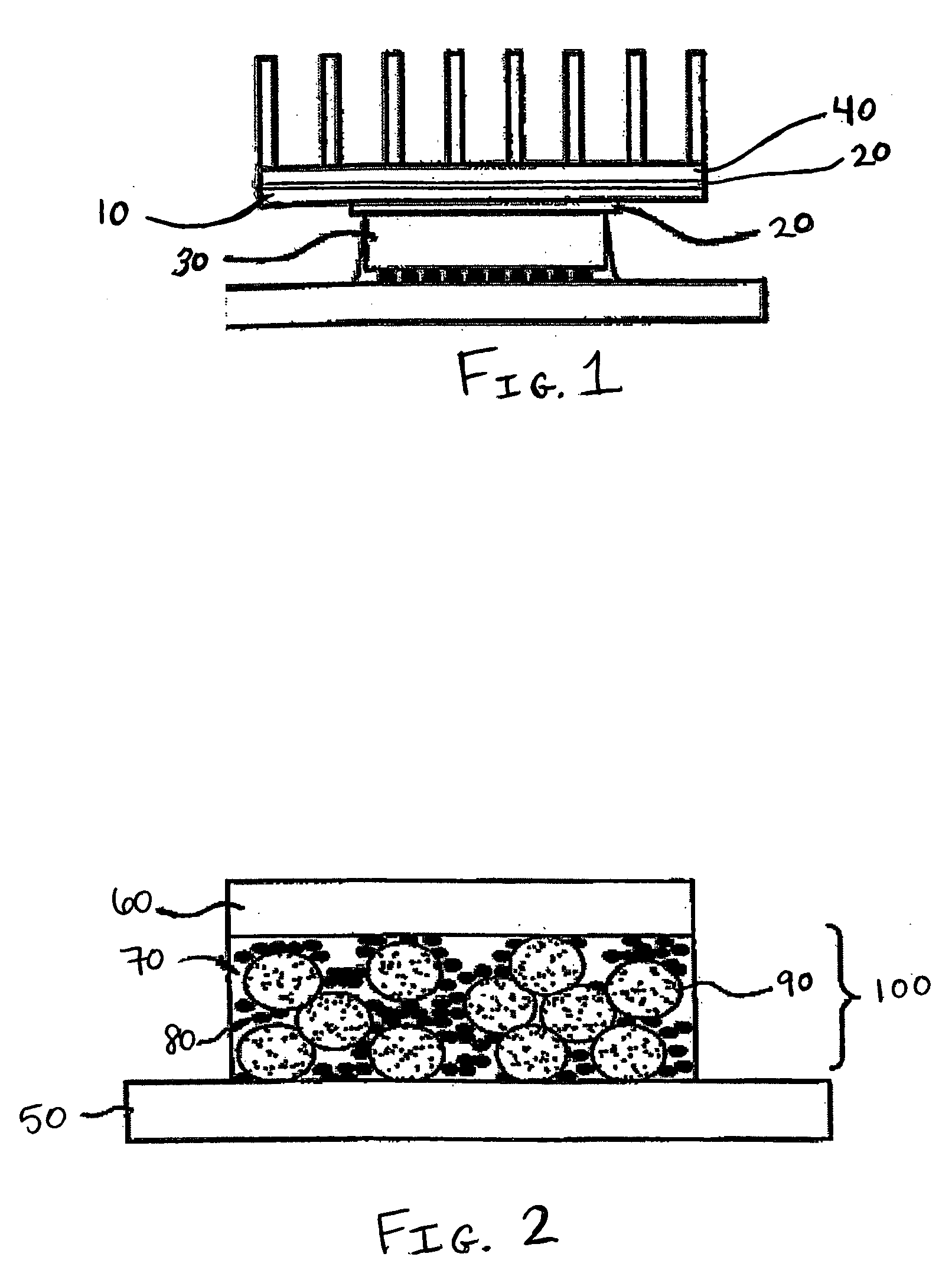
Image

Examples
example 1
[0047] A commercial grade of addition curable polydimethylsiloxane, ECC 4865 (4.29 grams, GE Silicones) was used as the matrix material. About 18.98 grams of gallium (Aldrich, 99.999%) was melted in an oven at a temperature of about 50° C. and added to the silicone. After stirring and dispersing the gallium in silicone, about 3.72 grams of aluminum oxide (Sumitomo's AA04, average particle size 0.4 μm) and a further 17.81 grams of aluminum oxide (Showa Denko's AS20, average particle size 21 μm) were added in small portions with stirring to ensure proper mixing. In the final mixture, the resin to liquid metal to solid filler ratio is 1: 4.42 : 5.02 by weight. The flowable gray mixture was poured into a 50 mm circular mold, degassed at 50° C. for 1 hour and cured in a Carver press at 150° C., under a pressure of 5000 pounds retained for 45 minutes. The final gray disc was measured to be 2.50 mm in thickness, and determined to be electrically non-conductive using an Ohmmeter. Thermal co...
example 2
[0048] The formulation of Example 1 was repeated but with a different ratio of components: 4.06 grams of ECC4865 were used as the matrix material. 25.57 grams of gallium were mixed with ECC4865 first. The liquid mixture was then mixed with 4.46 grams of Al2O3 (Sumitomo's AA04, average particle size 0.4 μm) and about 21.37 grams of Al2O3 (Showa Denko's AS20, average particle size 21 μm). In the final mixture, the resin to liquid metal to solid filler ratio is 1:6.30:6.36 by weight. The final cured disc measured 1.61 mm in thickness, and was determined to be electrically non-conductive by an Ohmmeter. The thermal conductivity was outside the calibration range for the machine, but was estimated to be around 3.00 W / mK at 100° C. The initial viscosity of the uncured formulation was 208,000±2000 cps at 2.5 rpm at room temperature.
example 3
[0049] The formulation of Example 1 was repeated but with a different ratio of components: About 3.58 grams of ECC4865 were used as the matrix material. About 19.50 grams of gallium were prepared with about 3.95 grams of Al2O3 (Sumitomo's AA04, average particle size 0.4 μm) and about 18.7 grams of Al2O3 (Showa Denko's AS20, average particle size 21 μm). In this instance, gallium was added last, and beading of gallium was observed. In the final mixture, the resin to liquid metal to solid filler ratio is 1:5.45:6.33 by weight. The final cured disc measured 2.58 mm in thickness, and was determined to be electrically non-conductive by an Ohmmeter. The sample underwent three thermal conductivity measurements at 100° C. which yielded an average value of about 2.75±0.01 W / mK. The initial viscosity of the uncured formulation was not measured.
PUM
| Property | Measurement | Unit |
|---|---|---|
| weight % | aaaaa | aaaaa |
| weight % | aaaaa | aaaaa |
| temperature | aaaaa | aaaaa |
Abstract
Description
Claims
Application Information