Method and system for probe optimization while instrumenting a program

a technology of program and probe, applied in the field of method and system for probe optimization while instrumenting a program, can solve the problems that the overhead of instrumentation/probes may outweigh the benefits of code coverage analysis, and the performance cost of probe-based analysis may be significant, so as to reduce the overhead of code coverage data collection and increase the performance of instrumented code.

Inactive Publication Date: 2005-10-13
MICROSOFT TECH LICENSING LLC
View PDF8 Cites 52 Cited by
  • Summary
  • Abstract
  • Description
  • Claims
  • Application Information

AI Technical Summary

Benefits of technology

[0005] The present invention provides a method and system for instrumenting a program by optimizing probe insertion. Optimizing the probe insertion increases performance of the instrumented code by reducing code coverage data collection overhead. The control flow of the code is analyzed along with the arc and block relationships to build a “post-dominator tree”. A post-dominator refers to a relationship between a first section of code and a second section of code. If the first section of code must execute before the second section of code can execute, the second section of code is referred to as the “post-dominator” of the first section of code. Correspondingly, in the same example, the first section of code is referred to as the “dominator

Problems solved by technology

The overhead imposed by the instrumentation/probes may outweigh the benefits of the code coverage analysis.
Th

Method used


Image

  • Method and system for probe optimization while instrumenting a program
  • Method and system for probe optimization while instrumenting a program
  • Method and system for probe optimization while instrumenting a program

Examples


Embodiment Construction

[0012] The present invention now will be described more fully hereinafter with reference to the accompanying drawings, which form a part hereof, and which show, by way of illustration, specific exemplary embodiments for practicing the invention. This invention may, however, be embodied in many different forms and should not be construed as limited to the embodiments set forth herein; rather, these embodiments are provided so that this disclosure will be thorough and complete, and will fully convey the scope of the invention to those skilled in the art. Among other things, the present invention may be embodied as methods or devices. Accordingly, the present invention may take the form of an entirely hardware embodiment, an entirely software embodiment or an embodiment combining software and hardware aspects. The following detailed description is, therefore, not to be taken in a limiting sense.

Illustrative Operating Environment

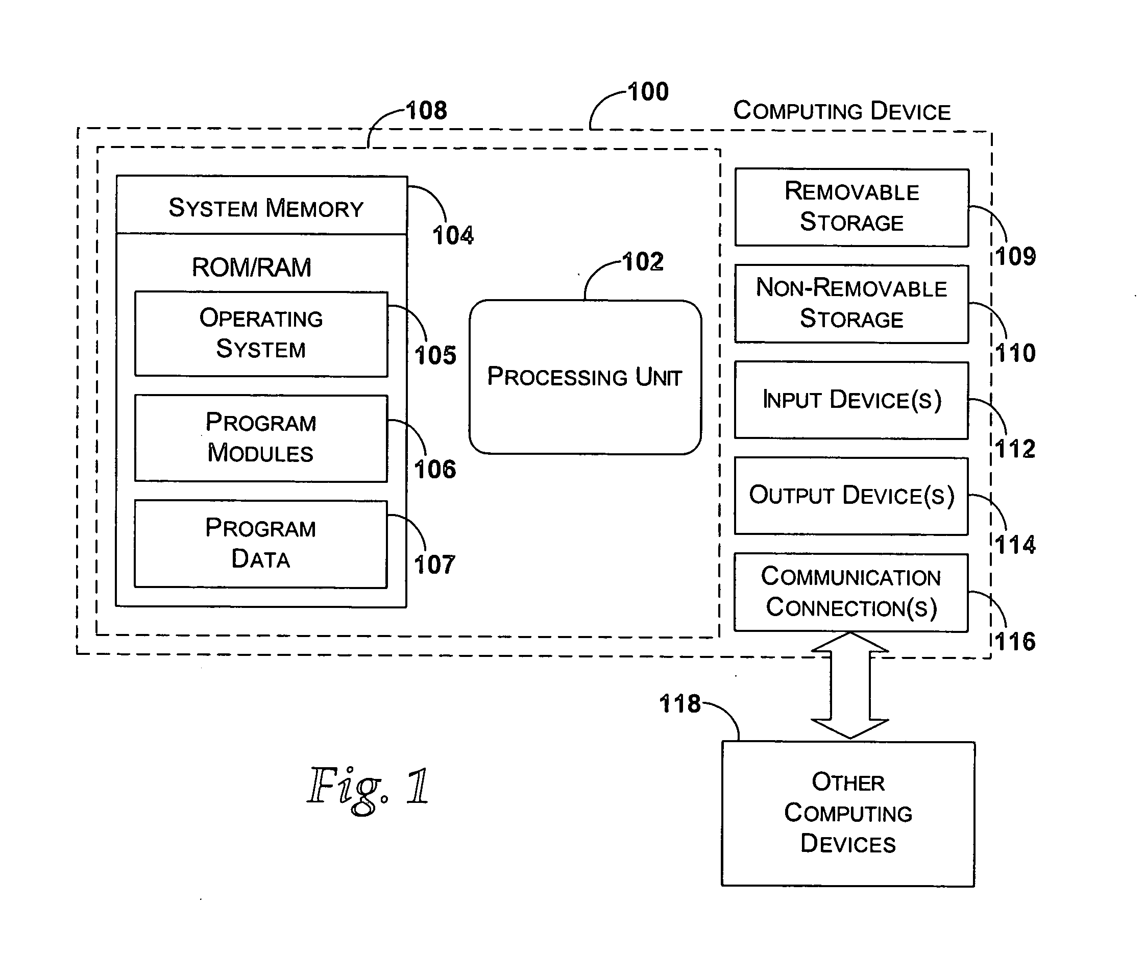
[0013]FIG. 1 shows an exemplary computing device that m...


PUM


Abstract

A method and system is provided for instrumenting a program by optimizing probe insertion. The number of probe insertions into instrumented code is reduced by providing optimal probe insertion points. The control flow of the code is analyzed along with the arc and block relationships to build a post-dominator tree. An optimization map is generated from the post-dominator tree that provides the optimal probe insertion points. Once the probes are inserted and data is collected by running the binary representing the code and probes, the data may be overlaid onto the optimization map and arc and block relationships to provide code coverage data.

Description

BACKGROUND OF THE INVENTION [0001] Coverage analysis is method adopted by many software developers for ensuring consistent, high-quality verification results. Code coverage analysis tools may be installed to provide the coverage analysis for a particular program. Coverage analysis tools may vary in scope and method for obtaining coverage information. [0002] Essentially, coverage analysis is based on the measurement of a design's test suite against a set of objective metrics. Designers will choose metrics based on the stage of their design, the cost of making the coverage measurement and a design group's experience with the usefulness of a particular metric. Code coverage metrics are often the first to be employed because they can be implemented at relatively low cost with automated tools and provide straightforward results. [0003] One method of code coverage instrumentation involves placing “probes” at each block or arc within the logical flow of a program's code. The “probes” refer...

Claims


Application Information

Patent Timeline
IPC IPC(8): G06F11/28G06F9/44G06F11/36
CPCG06F11/3676G06F9/06G06F11/22
Inventor MA, KENNETH KAI-BAUNSCHERTZ, STEPHEN CRAIG
Owner MICROSOFT TECH LICENSING LLC
Why Eureka
Try Eureka