Combustion engine of vertical shaft type

a combustion engine and vertical shaft technology, applied in machine/engines, valve drives, auxillary lubrication, etc., can solve the problems of increasing the oil temperature, troublesome and time-consuming to accomplish the servicing of the combustion engine, and the oil temperature may not be lowered as desired, so as to improve the separation of blow-by gases

Active Publication Date: 2005-10-20
KAWASAKI MOTORS LTD
View PDF6 Cites 21 Cited by
  • Summary
  • Abstract
  • Description
  • Claims
  • Application Information

AI Technical Summary

Benefits of technology

[0010] In view of the foregoing, the present invention has been devised to substantially eliminate the foregoing problems and inconveniences inherent in the conventional combustion engine and is intended to provide an improved combustion engine of a vertical shaft type, in which leakage of an oil from a crankcase and an oil pan is effectively prevented, which has high mounting rigidity relative to a working machine and, also, which is capable of being easily serviced.

Problems solved by technology

This structural feature poses the following problems: Specifically, in the conventional combustion engine, the surface level of an oil contained within the oil pan lies proximate to the plane of joint between the engine body and the mount base.
As an additional problem inherent in the conventional combustion engine, the thermal conduction from the oil pan to the cylinder block and the crankcase tends to be hampered by the presence of the gasket at the plane of joint and, therefore, the effect of cooling the oil pan through the cylinder block and the crankcase, both of which are air cooled, is so low that the temperature of the oil may not be lowered as desired.
Also, during the servicing of the combustion engine, the working machine is required to be separated from the combustion engine, followed by removal of the mount base from the engine body, and, accordingly, it is indeed troublesome and time-consuming to accomplish the servicing of the combustion engine.
Also, since a part of the governor gear is positioned to be immersed in the oil within the oil pan, the oil is stirred up, resulting in increase of the oil temperature.

Method used


Image

  • Combustion engine of vertical shaft type
  • Combustion engine of vertical shaft type
  • Combustion engine of vertical shaft type

Examples


Embodiment Construction

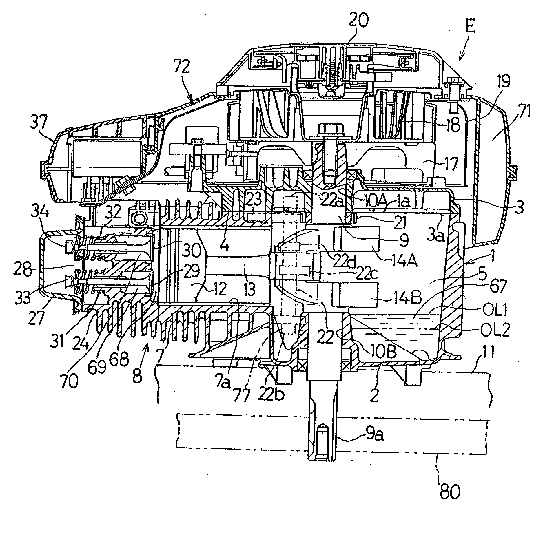
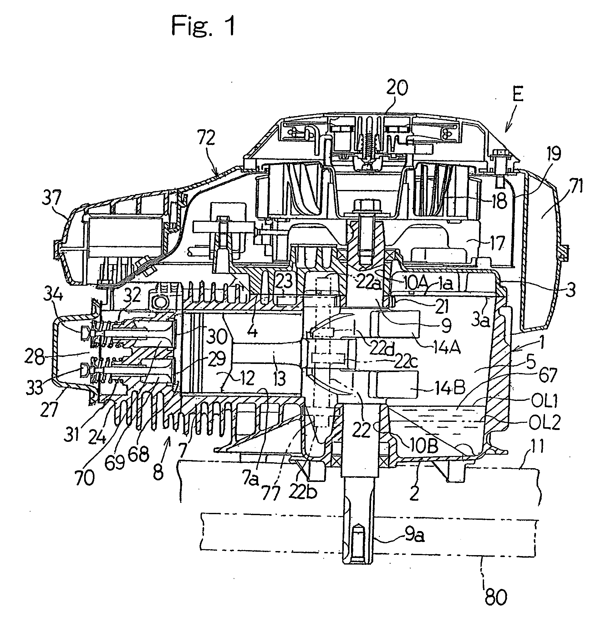
[0030] Reference will now be made to the accompanying drawings for the details of a preferred embodiment of the present invention. FIG. 1 illustrates, in a longitudinal sectional representation, a four-cycle vertical shaft type internal combustion engine E embodying the present invention. This combustion engine E includes an engine body 8 made up of a crankcase 1 and a cylinder block 7. The crankcase 1 includes an oil pan 2 formed integrally therewith, and a crankcase cover 3 is held in abutment with and fixed to an upper face 1a of the crankcase 1, with a gasket 4 intervening between it and the upper surface 1a of the crankcase 1. The cylinder block 7 is formed integrally with the crankcase 1 so as to protrude laterally forwards (or leftwards as viewed in FIG. 1) of the crankcase 1.

[0031] The crankcase cover 3 is mounted on an upper surface of the engine body 8 so as to cover a top opening of the crankcase 1 and a portion of the cylinder block 7. A crankshaft 9 is accommodated wit...


PUM


Abstract

To provide an internal combustion engine of a vertical shaft type, in which leakage of an oil from a crankcase and an oil pan is effectively prevented, which has high mounting rigidity relative to a working machine and, also, which is capable of being easily serviced, the combustion engine includes a vertically extending crankshaft (9) having a pair of upper and lower crank webs (14A and 14B), a crankcase (1) accommodating the crankshaft (9) and including an oil pan (2), and a crankcase cover (3) mounted on an upper surface (1a) of the crankcase (1) to cover the crankcase (1). The upper surface (1a) of the crankcase (1) is positioned above the upper crank web (14A).

Description

BACKGROUND OF THE INVENTION [0001] 1. Field of the Invention [0002] The present invention relates to a combustion engine of a vertical shaft type having a vertically extending crankshaft, which engine may be employed for driving a working machine such as a lawn mower. [0003] 2. Description of the Prior Art [0004] The conventional combustion engine of a vertical shaft type includes an engine body made up of a crankcase, in which a crankshaft is supported to extend vertically, and an engine cylinder block integrated together with the crankcase and accommodating a horizontally laid reciprocating piston, which is in turn drivingly connected to the crankshaft through a connecting rod. The engine body of the conventional combustion engine has a lower end face, with which a mount base serving to define both an oil pan of the engine and the mounting of a working machine such as a lawn mower is connected through a gasket. See, for example, the Japanese Utility Model Registration No. 2505523....

Claims


Application Information

Patent Timeline
Patent Type & Authority Applications(United States)
IPC IPC(8): F01L1/04F01M13/04F01M1/00F01M1/04F02B75/00F02F1/00F02F7/00F02M59/20F02M59/28
CPCF02B75/007F01M1/04
Inventor MIYAKE, HITOMIINOUE, TAKEMIUEMURA, ICHIROYAMAKAWA, TETSUHIRO
Owner KAWASAKI MOTORS LTD
Why Eureka
Try Eureka