Aerosol delivery apparatus and method for pressure-assisted breathing systems

Active Publication Date: 2005-10-20
NOVARTIS AG
View PDF22 Cites 36 Cited by
  • Summary
  • Abstract
  • Description
  • Claims
  • Application Information

AI Technical Summary

Benefits of technology

[0012] As with conventional CPAP operation, a constant flow of gas is maintained in the respiratory circuit by the CPAP system of the present invention during inhalation by the patient (hereinafter referred to as “inspiratory flow”). In the practice of the present invention, a flow corresponding to the inspiratory flow, but at a lesser flow rate, is diverted to the auxiliary circuit. An adjustable valve, e.g. an orifice valve, is preferably provided in the auxiliary circuit to regulate the flow of gas through the flow sensor. This valve may be used to reduce the flow of gas in the respiratory circuit to a range that can be measured by the flow sensor, and preferably in the middle of this range. Particularly preferred flow sensors have a flow range of from 0 to 1 liter/minute (“L/min”).
[0013] When the patient exhales, the flow of gas in the respiratory circuit (and correspondingly in the auxiliary circuit) increases as a result of the additional flow of gas generated by the patient's lungs (hereinafter referred to as “expiratory flow”). In a preferred embodiment, the flow sensor detects the change in the flow rate of gas in the auxiliary circuit corresponding to the expiratory flow in the respiratory circuit, and sends an electronic

Problems solved by technology

This waste, particularly with extremely expensive surfactants, makes the cost of administering

Method used


Image

  • Aerosol delivery apparatus and method for pressure-assisted breathing systems
  • Aerosol delivery apparatus and method for pressure-assisted breathing systems
  • Aerosol delivery apparatus and method for pressure-assisted breathing systems

Examples


example 1

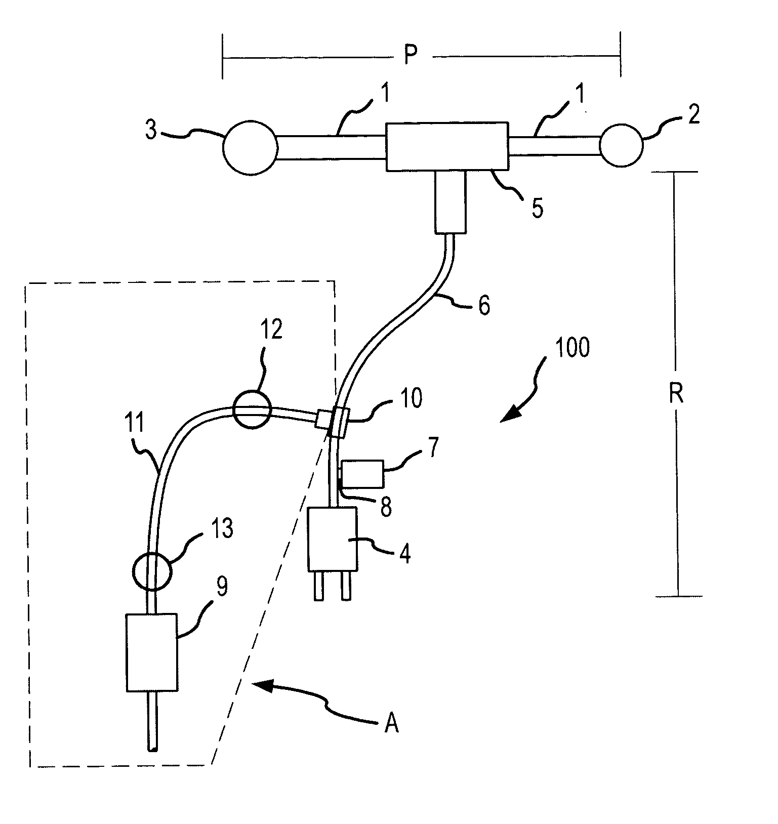
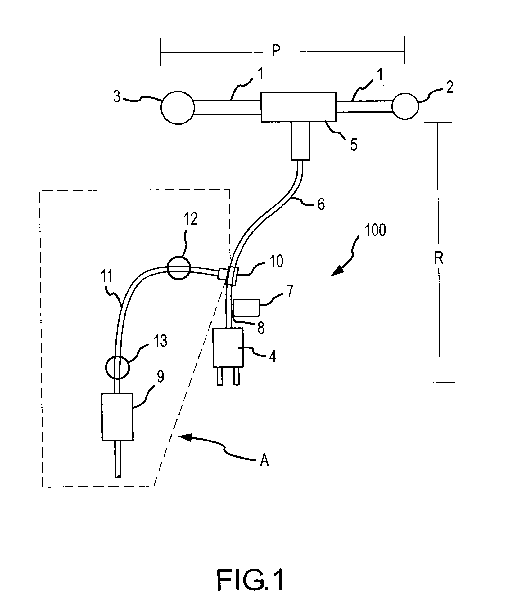
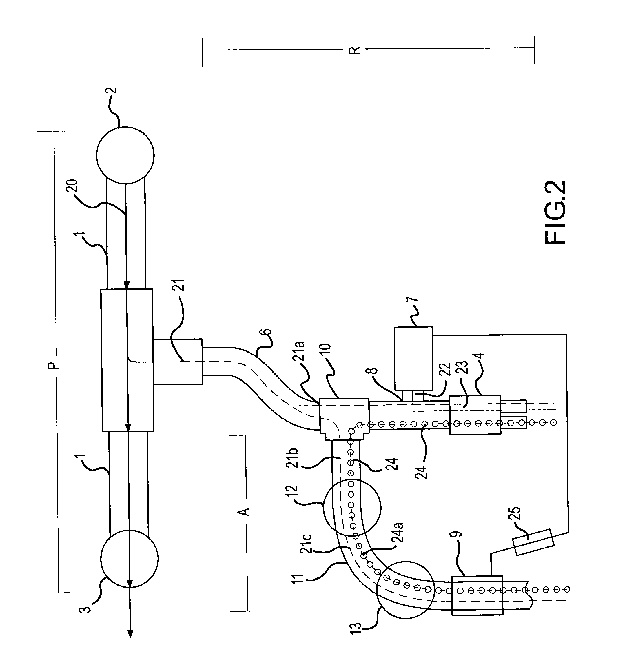
[0034] A CPAP system of the present invention such as illustrated in FIGS. 1 and 2 may be used for respiratory treatment of an infant. The system may be pressurized to a pressure of 5 cm H2O and a constant flow of air may be supplied by flow generator 2 into pressure-generating circuit P at a rate of 10 L / min. About 1 L / min (10%) of the air flow in pressure-generating circuit P may flow into flexible tube 6 as flow 21. During inhalation by the infant through nasal cannula 4, about 20% of flow 21 (identified in FIG. 2 as flow 21b) may be diverted into tube 11 at junction 10 by appropriately adjusting orifice valve 12 to produce a flow rate for flow 21c of about 0.2 L / min (0.2×1 L / min). Flow 21c may also pass through a disposable filter 13, but since flow 21c contains only inhalation air containing very little, if any, contamination, nothing significant should be removed from flow 21c by the filter. Flow 21c then may pass through the Omron flow sensor described above at a flow rate of...

example 2

[0037] Referring to FIG. 3, CPAP system 300 was attached to a breathing simulation piston pump 30 (commercially available from Harvard Apparatus, Holliston, Mass. 01746) to simulate an infant's breathing cycle. CPAP system 300 included auxiliary circuit A comprising pressure valve 38, disposable filter 39 and flow sensor 40 connected to respiratory circuit 42 through tube 43 in accordance with the present invention. A removable filter 31 was placed at the inlet of pump 30. An adapter 32 with two orifices 33 representing infant nares (Argyle nasal prong commercially available from Sherwood Medical, St. Louis, Mo. 63013) was connected to filter 31. Nebulizer 37 (Aeroneb® Professional Nebulizer System commercially available from Aerogen, Inc., Mountain View, Calif.) was placed in respiratory circuit 42 near adapter 32 so as to deliver an aerosolized drug into the air flow passing through orifices 33. During the operation of pump 30, air containing the entrained aerosolized drug flowed ...


PUM


Abstract

A pressure-assisted breathing system is provided that comprises: a pressure-generating circuit for maintaining a positive pressure within the system; a patient interface device coupled to a patient's respiratory system; a respiratory circuit for providing gas communication between the pressure-generating circuit and the patient interface device; means for introducing aerosol particles into the gas flow in the respiratory circuit; and means for discontinuing the introduction of aerosol particles into said respiratory circuit gas flow when the patient exhales. In one embodiment, a flow sensor is disposed in an auxiliary circuit in fluid communication with the respiratory circuit and electronically coupled with a nebulizer. The flow sensor is adapted to detect changes in the volumetric flow rate of gas in the auxiliary circuit when the patient exhales and stops exhaling and sends corresponding electronic signals to the nebulizer to turn off and turn on, respectively.

Description

CROSS-REFERENCES TO RELATED APPLICATIONS [0001] This application is a continuation-in-part of U.S. application Ser. No. 10 / 828,765, filed Apr. 20, 2004, and is related to U.S. application Ser. No. 10 / 883,115, filed Jun. 30, 2004, both of which are incorporated by reference herein in their entirety.STATEMENT AS TO RIGHTS TO INVENTIONS MADE UNDER FEDERALLY SPONSORED RESEARCH OR DEVELOPMENT [0002] NOT APPLICABLE REFERENCE TO A “SEQUENCE LISTING,” A TABLE, OR A COMPUTER PROGRAM LISTING APPENDIX SUBMITTED ON A COMPACT DISK [0003] NOT APPLICABLE BACKGROUND OF THE INVENTION [0004] This invention relates to apparatus and methods for delivering medication to the respiratory system of a patient, preferably an infant, through a pressure-assisted breathing system. More specifically, one aspect of the invention is directed to apparatus and methods for coupling a flow sensor with a continuous positive airway pressure (“CPAP”) system that employs a nebulizer, preferably one having a vibrating aper...

Claims


Application Information

Patent Timeline
IPC IPC(8): A61M11/00A61M15/00A61M16/00A61M16/08
CPCA61M11/005A61M15/0085A61M16/0666A61M16/08A61M16/0833A61M2016/0021A61M2016/0033A61M2205/7518A61M16/14A61M16/1055A61M16/1065
Inventor IVRI, EHUD
Owner NOVARTIS AG
Why Eureka
Try Eureka