
Charged particle beam apparatus and specimen holder

a technology of chargeable particles and beams, applied in the direction of instruments, heat measurement, machines/engines, etc., can solve the problems of inapplicability of these references, and achieve the effect of reducing erroneous operations

Inactive Publication Date: 2005-10-20
HITACHI HIGH-TECH CORP
View PDF3 Cites 38 Cited by
  • Summary
  • Abstract
  • Description
  • Claims
  • Application Information

AI Technical Summary

Benefits of technology

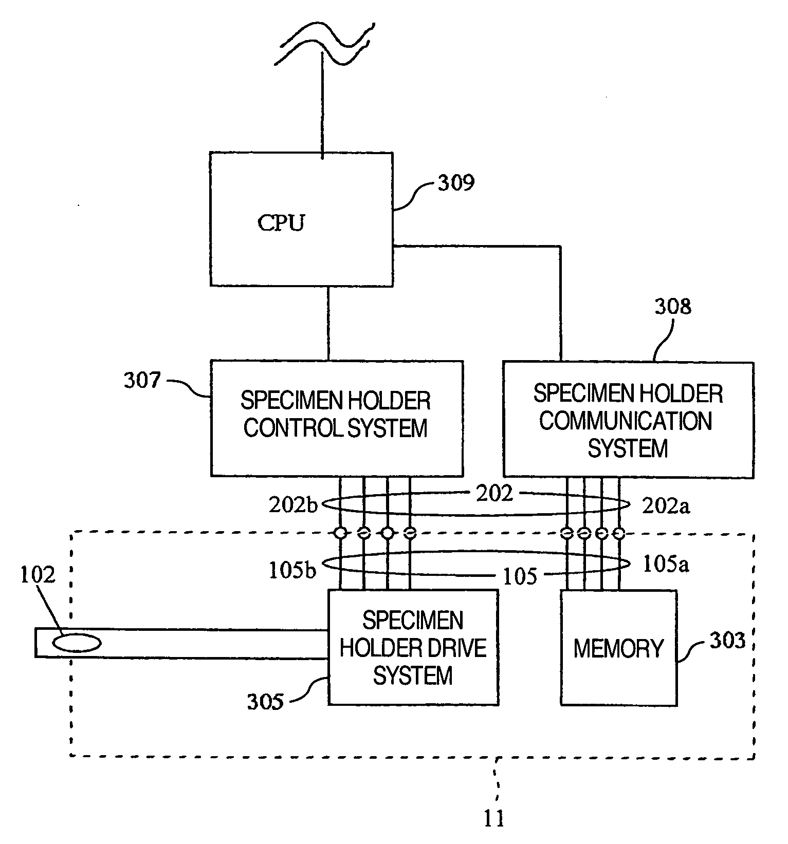
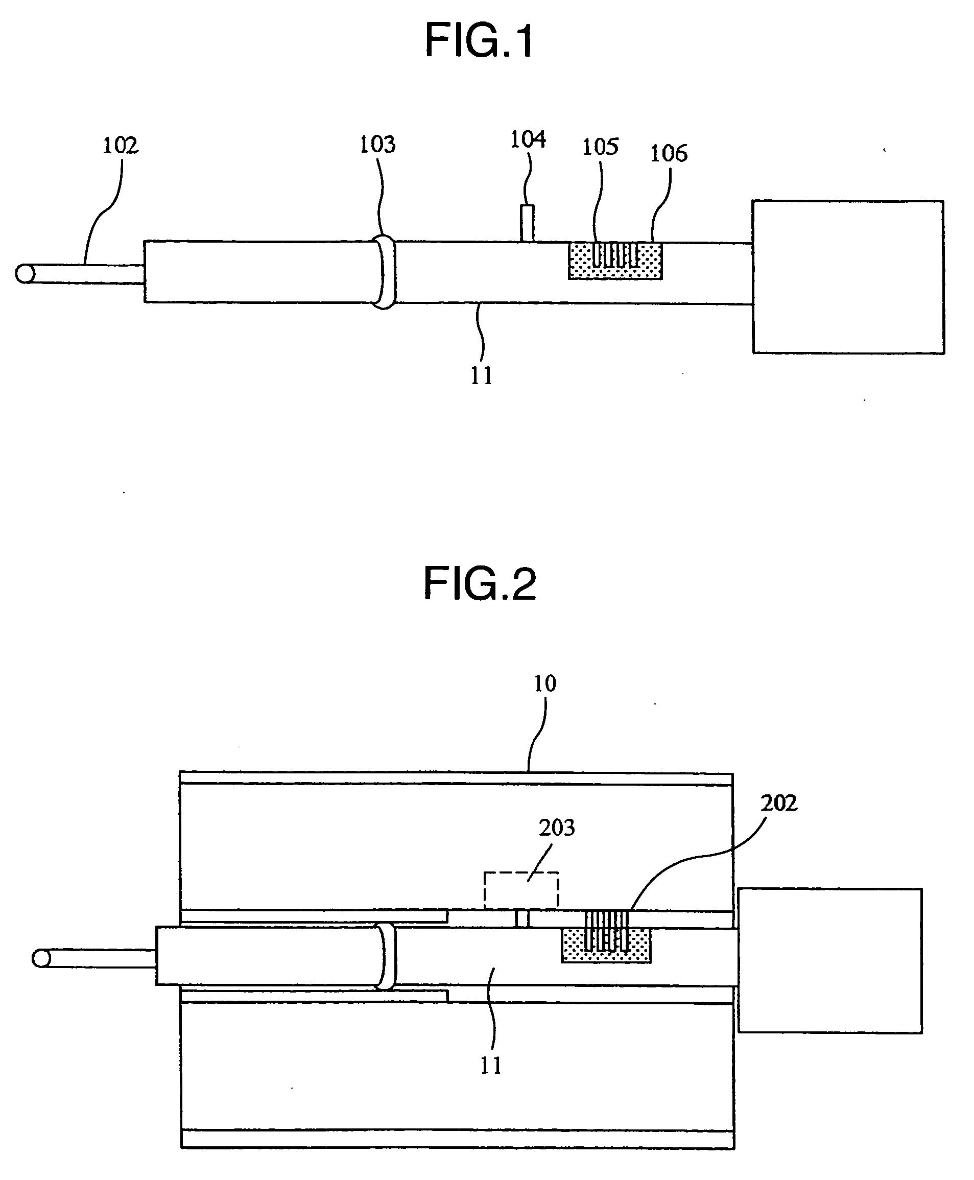
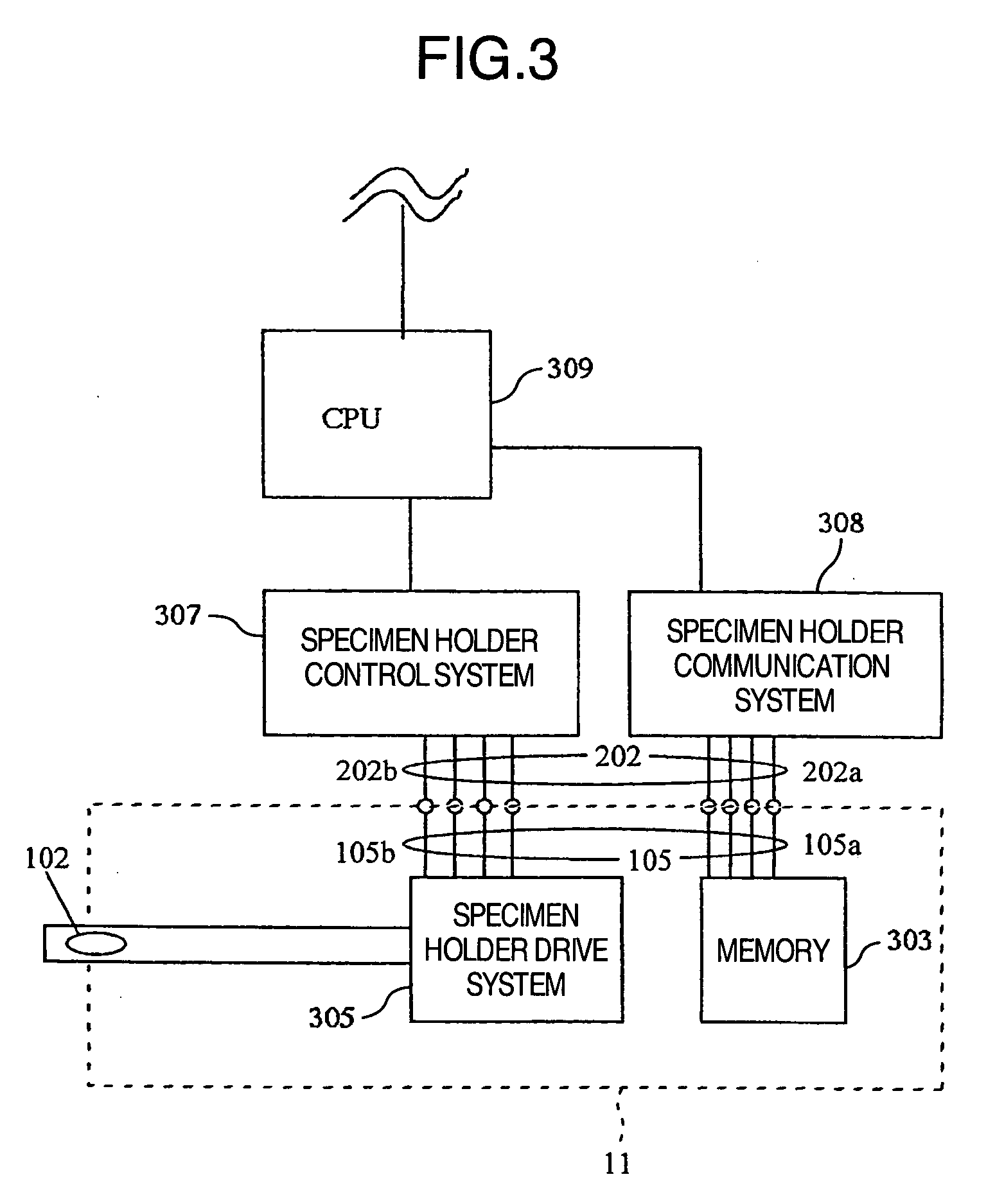
The present invention provides an electron microscope that can automatically acquire information about differences in specimen holders and specimens mounted on the holders, through recognition and memory by the user. This ensures more efficient operation. The electron microscope has a memory unit mounted on the specimen holder, which stores data inherent in the holder and information of the position observed for the last time. The apparatus can also control the specimen fine movement mechanism based on the information read from the memory. The memory can store information about the kind of the specimen holder and the mark for uniquely identifying it, as well as information about positions observed or worked with the electron microscope. This reduces the likelihood of user errors and ensures consistent operation. The specimen holder for use in an electron microscope can store information of the holder and the specimen mounted on it and transmit the information to the electron microscope. This simplifies the use of the electron microscope and ensures consistent operation.

Problems solved by technology

Neither Patent Document 1 nor Patent Document 2 takes into account a case that the specimen holder differs in kind or type, that a specimen mounted on a specimen holder has different levels of height or that a plurality of specimens are mounted on a single specimen holder and for this reason, techniques of these references are not practical.

Method used


Image

  • Charged particle beam apparatus and specimen holder
  • Charged particle beam apparatus and specimen holder
  • Charged particle beam apparatus and specimen holder

Examples


embodiment 1

[0032] Referring now to FIG. 8, there is illustrated in sectional schematic diagram form an example of side entry type specimen fine movement mechanism of a transmission type electron microscope. A first faucet 3 is hermetically fixed to the side of a column 1 of the transmission type electron microscope. Housed in the first faucet 3 is a specimen stage 10. A specimen holder 11 is slidably and airtightly inserted in a hole formed axially and centrally of the specimen stage 10. The specimen holder 11 has an end 11a convexly shaped in triangular pyramid form at which a specimen 8 is mounted (hereinafter referred to as a specimen mounting end). The specimen stage 10 has a fore end integral with a spherical member 9 which is supported by a concavely spherical surface 2 formed in the column 1. The specimen stage 10 is pivotal on a fulcrum in the center of spherical member 9 to perform a gooseneck motion.

[0033] On the other hand, a second faucet 14 is hermetically fixed to the side of co...

embodiment 2

[0063] Next, a charged particle beam apparatus capable of solving a problem which arises when a specimen mounted to a specimen holder is placed in a highly intensive focusing magnetic field or electric field and the specimen holder for use in the apparatus will be described.

[0064] In the present example, a specimen is handled in accordance with the following procedures. Firstly, the specimen is mounted to the specimen holder 11. Then, the specimen holder 11 carrying the specimen is inserted into a specimen height measuring device, not shown, for measuring the height of the specimen. In the specimen height measuring device, a laser beam, for instance, is irradiated onto the specimen surface and reflection light from the specimen is detected to measure a height of the specimen surface.

[0065] The present embodiment will be described by way of example of the height measurement based on laser beam irradiation but this is not limitative and the height may be measured using another type ...

embodiment 3

[0073] Next, a third embodiment will be described. When the specimen holder has the function to apply voltage, there is danger of electrical shock in the absence of a means for detecting whether the holder is laid internally or externally of the apparatus proper in the event that high voltage is applied to the holder before the holder is not yet inserted in the apparatus proper. The present example is directed to the protective function to prevent electrical shock in such an event.

[0074] A specimen holder 11 shown in FIG. 16 is equipped with a connector 1602 for admitting a high voltage 1601 and a cable connection sensor 1604 for deciding whether a cable 1603 is connected to the connector is annexed to the specimen holder 11. Then, with the specimen holder inserted in the electron microscope, the controller of electron microscope reads a state of memory device of the specimen holder 11 to decide whether the voltage is allowed to be applied to the specimen holder and only when the c...


PUM


Abstract

Information of a specimen holder or information of a specimen mounted on the specimen holder is stored in a memory inside the specimen holder mounted to an electron microscope. The memory is accessed to transmit the information of the specimen holder to the electron microscope, thereby ensuring that the user can use the specimen holder without mistaking characteristics of the specimen holder and danger of erroneous recording of the specimen information can be reduced.

Description

BACKGROUND OF THE INVENTION [0001] The present invention relates to a charged particle beam apparatus such as electron microscope and focused ion beam apparatus and a specimen holder used in the charged particle beam apparatus. [0002] In the case of a specimen holder for use in a conventional electron microscope, its size and function must be recognized by a user so that the user may operate the electron microscope in compliance with the holder. In addition, the user must memorize individually pieces of information of specimens mounted or carried on the specimen holder. JP-A-11-258130 (Patent Document 1) describes that a character or mark for identifying a specimen is inscribed on a specimen holder. [0003] Further, JP-A-2001-291483 (Patent Document 2) describes that a memory means is provided in a cartridge mounted to a specimen holder and pieces of information concerning a portion to be worked and a portion to be observed are stored in the memory means. SUMMARY OF THE INVENTION [00...

Claims


Application Information

Patent Timeline
Patent Type & Authority Applications(United States)
IPC IPC(8): G21K5/08G21K7/00H01J37/20
CPCH01J37/20H01J2237/208H01J2237/20292H01J2237/2001
Inventor TANAKA, HIROYUKISATO, MITSUGUSASAKI, MASASHITANIGUCHI, YOSHIFUMI
Owner HITACHI HIGH-TECH CORP
Learn More