Method and apparatus for manufacturing of beads for artificial pearls

Inactive Publication Date: 2005-10-20
RHEE YOUNG NAM +1
7 Cites 6 Cited by

AI-Extracted Technical Summary

Problems solved by technology

This conventional method and apparatus for manufacturing artificial pearl beads makes use of pressure, which has many problems.
2) The beads are produced only by primary moulding, so that there is a high possibility of air or gas generating bubbles in the bead.
Furthermore, even a surface of the bead is provided with such bubbles or cracks.
3) It is the most important problem that harmful gases generated when the urea resin are cured by hot heat are not properly discharged, thus being responsible for...

Method used

[0034] In the manufacturing method and apparatus of the present invention, the lower mould 400 is adapted to move up and down, it is because it is convenient to pour a powdered material for beads onto the flat lower mould 400 and because it is possible to prevent the bead material from being scattered when the lower mould moves up.
[0045] When the gas discharge process is completed, the lower mould that has moved down moves up again. Thereby, the lower mould comes into contact with the upper mould, so that secondary molding of the beads is completed (see FIG. 6). The secondary molding is for eliminating air bubbles caused b...

Benefits of technology

[0017] Therefore, the present invention has been made in view of the above-mentioned problems. The present invention is directed to provide a method and apparatus for manufacturing beads for artificial pearls, in which an ascent speed of a lower mould is automatically maintained to be constant using a cylinder driving means for moving up and down a lower mould for molding beads with holes by means of air or hydraulic pressure...

Abstract

In the method, an upper mould is fixed on an upper portion of a base body, and a lower mould is provided. When the primary molding is performed, the lower mould moves up at a different speed. The beads are drilled during the primary molding. After the primary molding, the lower mould moves down slightly. Gases generated while a material for the beads is cured are discharged, and the lower mould moves up to secondarily mold the beads. The lower mould is positioned on a pin plate fixed to a piston shaft of a cylinder. Semi-circular recesses of the lower mould are provided with pin holes. While pins fitted into the pin plate enters into and exits from the pin holes, the beads are drilled. The pin plate moves down by descent of the lifting plate, and thus the pins escape from the molded beads.

Application Domain

Technology Topic

Image

  • Method and apparatus for manufacturing of beads for artificial pearls
  • Method and apparatus for manufacturing of beads for artificial pearls
  • Method and apparatus for manufacturing of beads for artificial pearls

Examples

  • Experimental program(1)

Example

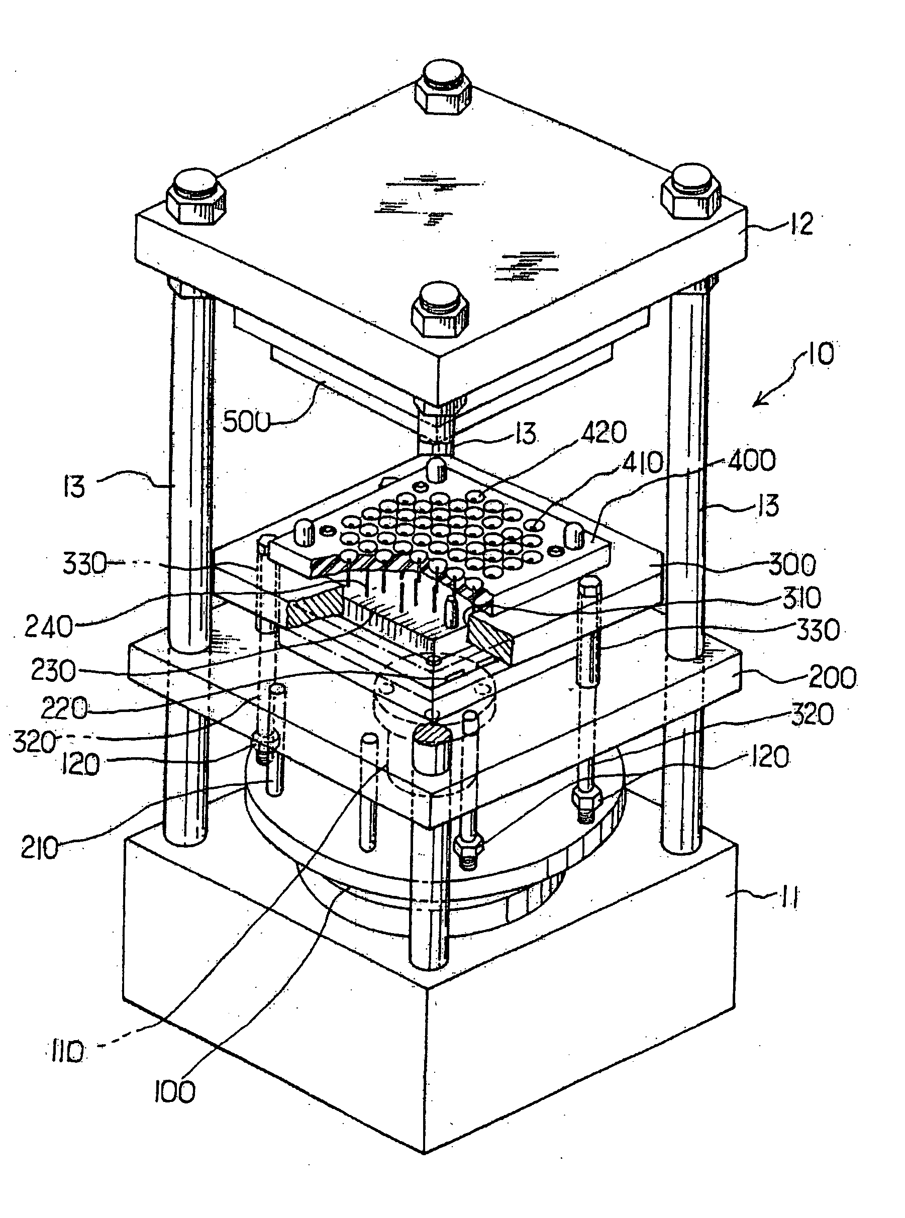
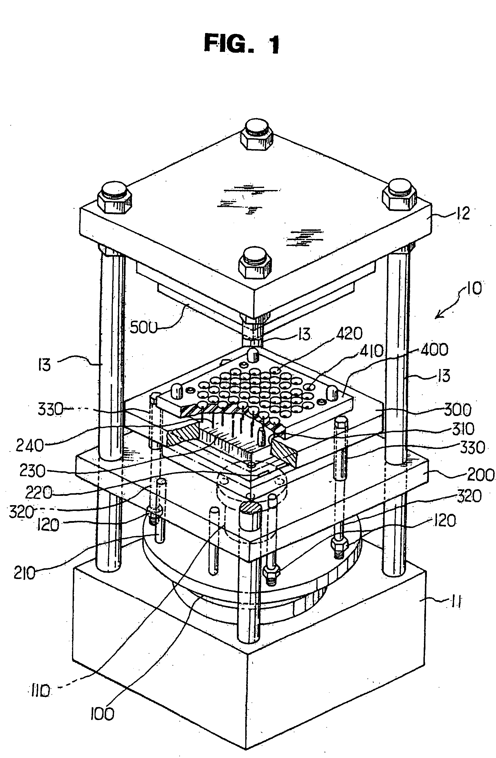
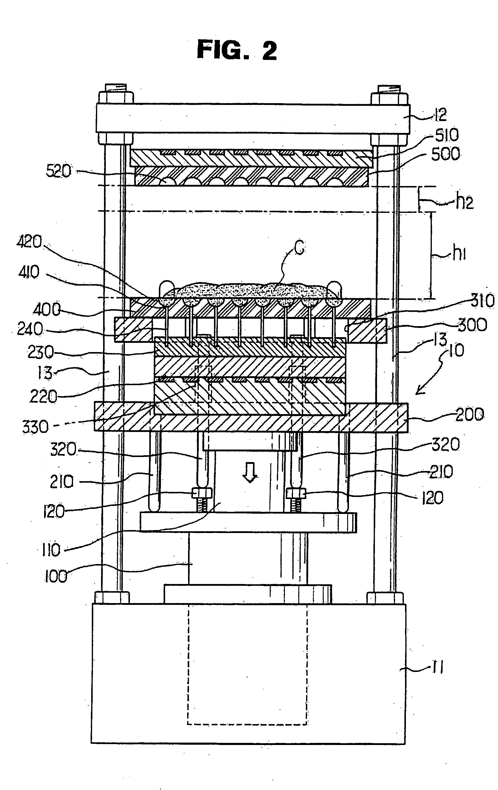
[0031] Hereinafter, a detailed description will be made about a configuration of an apparatus for manufacturing artificial pearl beads according to an exemplary embodiment of the invention with reference to the accompanying drawings.
[0032] A base body 10 is provided with guide posts 13 fixedly connecting corners of a lower base 11 and an upper base 12. A cylinder 100 has a piston shaft 110 installed in a middle of the lower base 11 and exposed outside, and is provided with height adjusting bolts 120. A lifting guide plate 200 is fixed to the piston shaft 110 of the cylinder 100 and moves up and down with the guide posts 13 inserted therein. A plurality of lifting guide plate supporting rods 210 are fixedly installed at several places under the lifting guide plate 200. At least one lower mould heating panel 220 is fixed to the lifting guide plate 220. A pin plate 230 is fixedly positioned on the lower mould heating panel 220 and is provided with a plurality of bead drilling pins 240. An intermediate plate 300 is provided with a gate 310 allowing of entrance and exit of the pin plate 230, a plurality of intermediate plate supporting rods 320 fixed at several places on a bottom surface thereof, and a spacing pipe 330 adjusting an interval between the intermediate plate and the lifting guide plate with the intermediate plate supporting rods inserted. A lower mould 400 is provided with a plurality of pin holes 410 into which the bead drilling pins 240 of the pin plate 230 are inserted and a plurality of semi-circular lower mould bead molding recesses 420 communicating with the plurality of pin holes 410. An upper mould 500 is fixed to an upper mould heating panel 510 installed on the upper base 12 of the base body 10 and is provided with a plurality of semi-circular upper mould bead molding recesses 520.
[0033] The cylinder 100 is driven by air or hydraulic pressure. Lifting distance and speed of the piston 110 are adjusted by a computer program or by manipulating a manual valve.
[0034] In the manufacturing method and apparatus of the present invention, the lower mould 400 is adapted to move up and down, it is because it is convenient to pour a powdered material for beads onto the flat lower mould 400 and because it is possible to prevent the bead material from being scattered when the lower mould moves up.
[0035] Hereinafter, effects of the manufacturing method and apparatus of the present invention will be described.
[0036] As in FIGS. 1 and 2, in the state where the piston shaft 110 moves down and thereby the lower mould 400 moves down, a proper amount of urea resin powder c is poured onto a flat upper surface of the lower mould 400 (see FIG. 2).
[0037] The amount of the urea resin powder c is determined according to a volume of the semi-circular bead molding recesses 520 and 420, which are provided to the upper and lower mould 500 and 400, respectively. The upper and lower mould 500 and 400 are mounted with the heating panels 510 and 220, so that the urea resin is cured by heat while the beads are molded.
[0038] The pins 240 fixed to the pin plate 230 are closely fitted into the pin holes 410 of the lower mould 400. Therefore, the lower mould is supported by the pins, and only a forced force causes the pins to escape from the pin holes.
[0039] Accordingly, when the pins escape from the molded beads as in FIG. 2, a predetermined interval is generated between the pin plate and the lower mould. Even in this state, the pins 240 are closely fitted into the pin holes 410 of the lower mould. Thus, the lower mould can move up and down with the interval kept to be constant with respect to the pin plate.
[0040] In the case of the lower mould, primary ascent movement is done by primary ascent interval h1, and preferably an ascent speed is between about 10 and 30 cm per second. However, the urea resin is not scattered even at the ascent speed between about 30 and 50 cm per second.
[0041] After the primary ascent movement, an upper surface of the lower mould reaches a start point of a secondary ascent interval h2. At this point, the ascent speed is lowered less than 10 cm per second. Alternately, the ascent speed may be between about 10 and 15 cm per second.
[0042] When the lower mould 400 moves up to come into contact with the upper mould 500, the urea resin is inserted into the semi-circular bead molding recesses 520 and 420 of the upper and lower moulds. Then, the urea resin is cured to primarily mold the beads. Next, the pin plate 230 moves down to push up the pins 240 by the interval escaping from the semi-circular bead molding recesses 420 of the lower mould 400. Thereby, the pins enter into the semi-circular bead molding recesses of the lower and upper moulds, so that the primarily molded beads are drilled.
[0043] A primary molding time of the beads is determined according to standard of the beads and temperature of the moulds, but preferably determined between about 3 and 5 seconds when the beads have a diameter of about 1 cm.
[0044] When the primary molding of the beads is completed, harmful gases generated from the urea resin are discharged. In this process, among the upper and lower moulds coming into contact with each other, the lower mould 400 moves down by a gas discharge interval h3 as the piston shaft moves down. The harmful gases are discharged through the gas discharge interval h3. In this case, the gas discharge interval h3 is preferably between about 5 and 10 mm. To this end, when the gas discharge interval h3 is narrow, the gas discharge time is lengthened. When the gas discharge interval h3 is wide, the gas discharge time is shortened.
[0045] When the gas discharge process is completed, the lower mould that has moved down moves up again. Thereby, the lower mould comes into contact with the upper mould, so that secondary molding of the beads is completed (see FIG. 6). The secondary molding is for eliminating air bubbles caused by gases and air contained in the primarily molded beads to thus enhance a density of the bead.
[0046] When the secondary molding of the beads is completed, the lifting guide plate 200, the intermediate plate 300 and the lower mould 400 move down along the piston shaft. At this time, the lower mould and the pin plate 230 continue to be in close contact with each other, and the pins 240 of the pin plate are in the state of passing through the molded beads.
[0047] Subsequent to this state, lower ends of the intermediate plate supporting rods 320 fixed under the intermediate plate 300 reach the height adjusting bolts 120, the intermediate plate does no longer move down. Further, both the pin plate fixed to the lifting guide plate 200 and the lower mould moves down along the lifting guide plate, but stops to move down in a state of resting on the intermediate plate without passing through the gate 310 of the stopped intermediate plate 300. Meanwhile, the pin plate passing through the gate 310 of the intermediate plate 300 moves down along the lifting guide plate 200, and thereby the lower mould stops to move down. Therefore, the pin plate moves down, and the pins escape from the beads to bottoms of the bead molding recesses of the lower mould. At this time, the lifting guide plate supporting rods 210 fixed under the lifting guide plate come into contact with an upper surface of the flange of the cylinder, so that the lifting guide plate and the pin plate do no longer move down, the beads from which the pins have escaped are collected from the lower mould (see FIG. 8).
[0048] The intermediate plate supporting rods 320, which are fixed under the intermediate plate 300, pass through the lifting guide plate. A spacing plate 340 is fitted into the intermediate plate supporting rods 320 between the lifting guide plate and the intermediate plate. Thus, when moving up or down, the interval between the lifting guide plate and the intermediate plate is maintained. The height adjusting bolts 120 installed to the cylinder flange adjust a height so that, when the pin plate 230 moves down, the pins 240 of the pin plate safely escape from the lower mould bead molding recesses 420. The height adjusting bolts 120 are adjusted according to a thickness of the lower mould and a size of the bead molding recess.
[0049] The beads manufactured by the method and apparatus are subjected to a surface polishing process and are painted on its surface with a pearl solution, thereby being finished as artificial pearls.
[0050] Further, it is possible to manufacture the beads without holes using the method and apparatus of the present invention. Thus, when the lower mould having semi-circular bead molding recesses without pin holes is fixed to the lower mould, it is possible to produce the beads without pin holes.
[0051] According to the present invention implemented by the method and apparatus, the molding process of the beads is carried out automatically, so that it is possible to mass-produce the beads at a high quality. Further, it is possible to sharply reduce a labor force needed to produce the beads. The beads produced by the primary and secondary moldings have a good quality, and the harmful gases generated from the fundamental material of the beads are removed automatically, so that it is possible to produce the nonpolluting beads.
[0052] The foregoing embodiment and advantages are merely exemplary and are not to be construed as limiting the present invention. The present teaching can be readily applied to other types of apparatuses. Also, the description of the embodiments of the present invention is intended to be illustrative, and not to limit the scope of the claims, and many alternatives, modifications, and variations will be apparent to those skilled in the art.

PUM

PropertyMeasurementUnit
Length0.005m
Length0.03m
Speed0.1m / s
tensileMPa
Particle sizePa
strength10

Description & Claims & Application Information

We can also present the details of the Description, Claims and Application information to help users get a comprehensive understanding of the technical details of the patent, such as background art, summary of invention, brief description of drawings, description of embodiments, and other original content. On the other hand, users can also determine the specific scope of protection of the technology through the list of claims; as well as understand the changes in the life cycle of the technology with the presentation of the patent timeline. Login to view more.

Similar technology patents

Whey protein powder prepared by taking milk as raw material and preparation method thereof

InactiveCN101731446AReduce contentLow costProtein composition from milkChemistryWhey protein powder
Owner:INNER MONGOLIA YILI INDUSTRIAL GROUP CO LTD

Classification and recommendation of technical efficacy words

  • Reduce content
  • Reduce quality

Waterproof/sealing paint with aqueous resin as main body

Owner:漳州市奈特新型建材有限责任公司

System and method for providing handover of a mobile IP terminal in a wireless network

ActiveUS20050163080A1Longer battery timeReduce qualityAssess restrictionNetwork topologiesMIP protocolMobile internet
Owner:POSTECH ACAD IND FOUND

Display Device

ActiveUS20150362776A1Reduce qualityIncrease of surface irregularityPrinted circuit aspectsSolid-state devicesInput/outputEngineering
Owner:SEMICON ENERGY LAB CO LTD
Why Eureka
Try Eureka