Display device
a display device and display technology, applied in static indicating devices, electroluminescent light sources, instruments, etc., can solve the problems of power consumption increase and the entire screen illumination, and achieve the effect of reducing the display time rate of pixels, preventing the increase in the power consumption of display means, and increasing the display time ra
- Summary
- Abstract
- Description
- Claims
- Application Information
AI Technical Summary
Benefits of technology
Problems solved by technology
Method used
Image
Examples
embodiment 1
[0075] As shown in FIG. 10, a digital signal input active matrix EL display panel 9 using an EL element in a pixel has a pixel portion 9a including a pixel 9b arranged in matrix, and a source signal line driver circuit 10, a writing gate signal line driver circuit 11, and an erasing gate signal line driver circuit 12 that are disposed at the periphery of the pixel portion 9a. The source signal line driver circuit 10 has a shift register 10a, a latch 10b, a latch 10c, and a level shifter buffer 10d. The gate signal line driver circuits 11 and 12 have shift registers 11a and 12a respectively.
[0076] The pixel portion 9a further has source signal lines (S1 to Sn) connected to the level shifter buffer 10d of the source signal line driver circuit 10, writing gate signal lines (G11 to G1m) connected to the shift register 11a of the writing gate signal line driver circuit 11, and erasing gate signal lines (G21 to G2m) connected to the shift register 12a of the erasing gate signal line driv...
embodiment 2
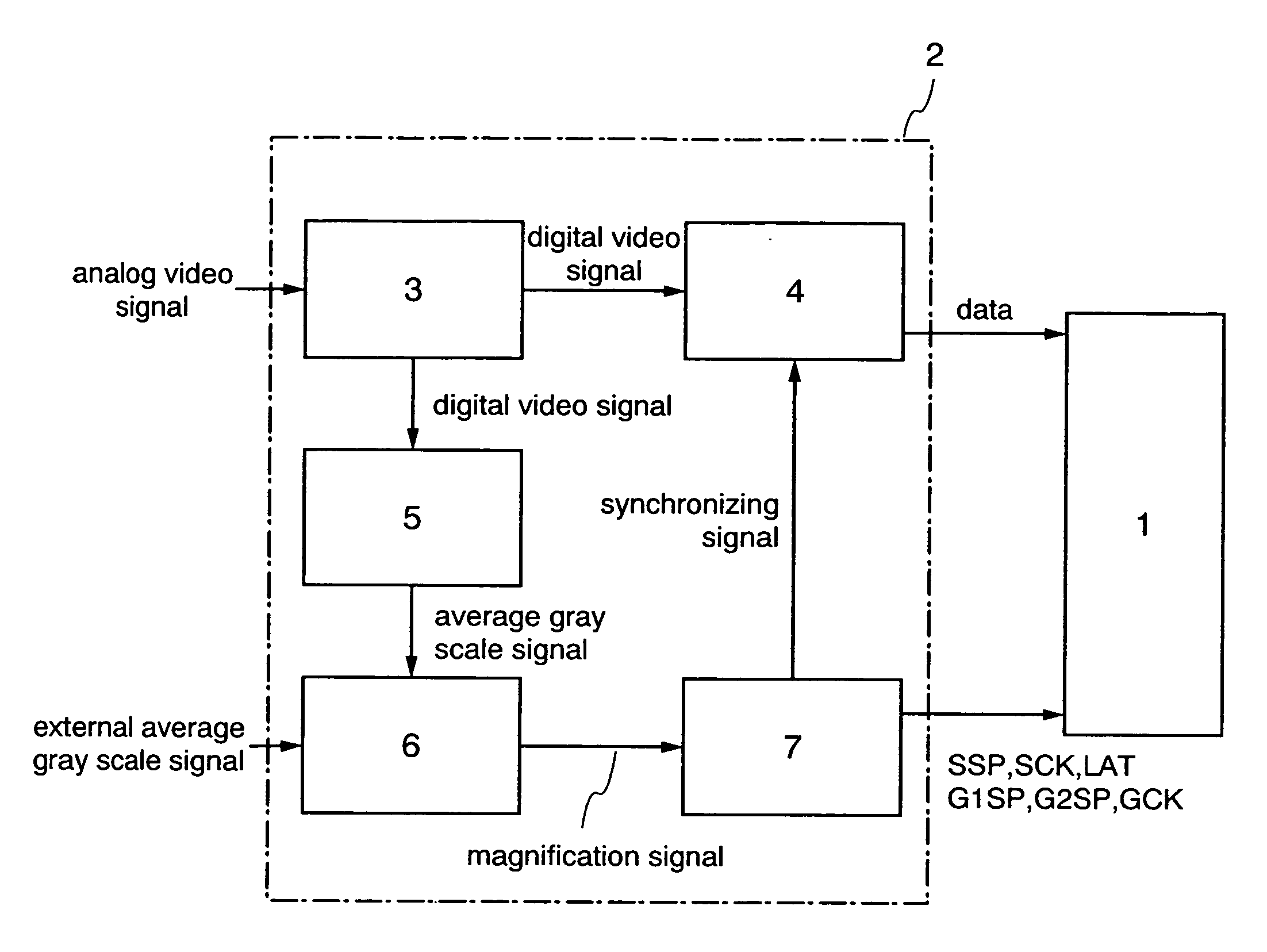
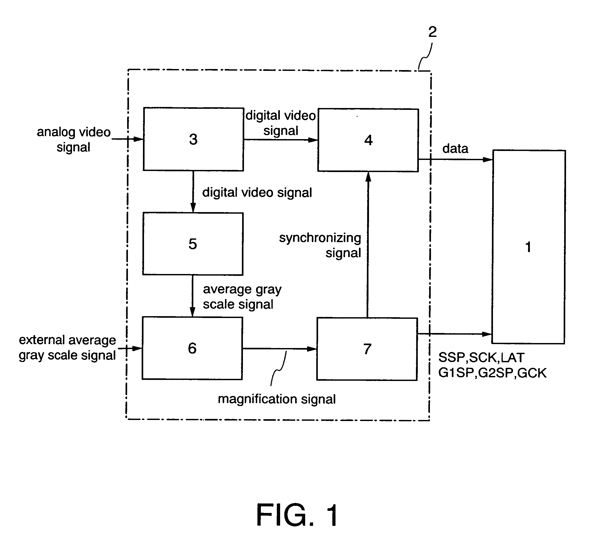
[0087] Described is an embodiment of gray scale control using the aforementioned table in the case where an analog signal is inputted to the display means as a video signal. When an analog signal is inputted as a video signal, a D / A converter is provided in the data controller 4 in the block diagram shown in FIG. 1, and a video signal converted into a digital signal by the A / D converter 3 is converted into an analog signal by the D / A converter. The other components in FIG. 1 can be utilized as they are. Since the magnification signal of the table shown in Table 1 is employed, an erase start signal generating circuit for generating an erase start signal GSP is described hereinafter with reference to FIG. 4. As shown in FIG. 4, the erase start signal generating circuit has the counter 8a, the accumulator 8b, the EXNOR circuits 8c, the AND circuit 8d, and an OR circuit 8e. The counter 8a counts a writing clock GCK using a scan start signal G1SP for writing to a pixel as a reset signal ...
embodiment 3
[0098] The aforementioned embodiment using an analog video signal as video data, which is applied to the display panel including an EL element in a pixel, can also be applied to a liquid crystal display panel including a liquid crystal in a pixel. Since a display panel including a liquid crystal in a pixel is voltage driven, a video data is inputted to the source signal line driver circuit 19 after being D / A converted into a voltage value corresponding to the display panel. According to this, even in the case of using a liquid crystal element instead of the EL element, the invention can be implemented similarly using the gray scale control circuit.
[0099] The display device of the invention where the gray scale level of the display means is controlled by the gray scale control circuit can be applied to electronic apparatuses such as a video camera, a digital camera, a goggle type display (head mounted display), a navigation system, an audio reproducing device (car audio set, audio c...
PUM
| Property | Measurement | Unit |
|---|---|---|
| display time rate | aaaaa | aaaaa |
| time rate | aaaaa | aaaaa |
| luminescence | aaaaa | aaaaa |
Abstract
Description
Claims
Application Information
 - R&D
- Intellectual Property
- Life Sciences
- Materials
- Tech Scout
- Unparalleled Data Quality
- Higher Quality Content
- 60% Fewer Hallucinations
Browse by: Latest US Patents, China's latest patents, Technical Efficacy Thesaurus, Application Domain, Technology Topic, Popular Technical Reports.
© 2025 PatSnap. All rights reserved.Legal|Privacy policy|Modern Slavery Act Transparency Statement|Sitemap|About US| Contact US: help@patsnap.com


