
Method and apparatus for recording hologram, method and apparatus for reproducing hologram, and information retaining body

a technology for recording holograms and information retaining bodies, which is applied in the field of methods and apparatus for recording holograms, methods and apparatus for reproducing holograms, and information retaining bodies, which can solve the problems of limited recognition performance and conversion speed, and the above-described two-dimensional code and semiconductor chips only have storage capacity

Inactive Publication Date: 2005-10-20
FUJIFILM BUSINESS INNOVATION CORP
View PDF2 Cites 40 Cited by
  • Summary
  • Abstract
  • Description
  • Claims
  • Application Information

AI Technical Summary

Benefits of technology

[0021] In accordance with the present invention, even in the case of an information retaining body in which the holographic recording layer is supported on a support body having a surface of less than optical quality, the light beam scattered on the surface

Problems solved by technology

Information on the electronic media can be converted into information on the paper media by “printing.” However, digital information of the electronic media may be lost during a printing process.
However, in the technique for recognizing an image, there are limits with respect to recognition performance and conversion speed.
However, the above-described two-dimensional code and semiconductor chip only have a storage capacity as small as several hundred bytes.
Although this storage capacity is enough for the URL information or the ID information, the storage capacity is not sufficient for the utilization of various kinds of information.
Further, the information is transmitted by wireless communication, so that a mechanism on the information retaining media side and an encryption technique tend to be complicated.
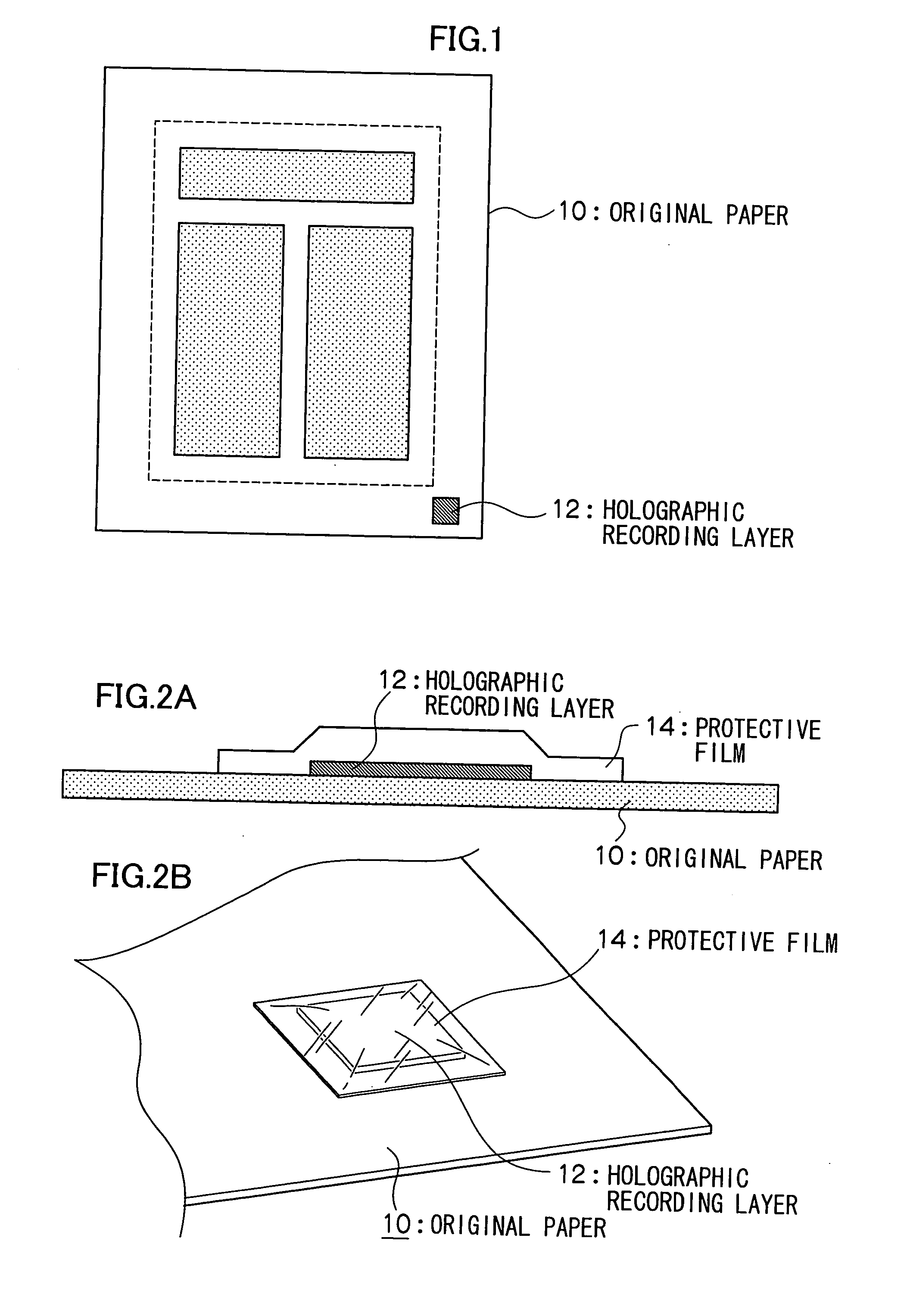
However, because the hologram, in which a signal light beam (object light beam) is recorded, is irradiated with a reference light beam to reproduce the signal light beam by diffraction from the hologram, there is a problem in that the signal light beam cannot be read with a high S / N ratio due to diffuse reflection on a surface of the sheet member or flexure of the sheet member, when the holographic recording layer is bonded onto a sheet member having a non-optical quality such as paper or a plastic card.
As a result, reading errors are increased.
However, the reference light beam is scattered on the surface of the sheet member, and the reproduced signal light beam is submerged in the scattered light beam, so that the reproduced signal light beam can not be detected.
However, in the information retaining body whose periphery is rigidly formed so that the holographic recording layer is not deformed, conformity between a holographic memory and a support body is lost and a sense of usefulness is largely lost.

Method used


Image

  • Method and apparatus for recording hologram, method and apparatus for reproducing hologram, and information retaining body
  • Method and apparatus for recording hologram, method and apparatus for reproducing hologram, and information retaining body
  • Method and apparatus for recording hologram, method and apparatus for reproducing hologram, and information retaining body

Examples


example 1

(EXAMPLE 1)

[0102] The commercial photopolymer film “OmniDex” (trademark, product of DuPont) having the layer structure shown below is cut into a small chip having a size of 50 mm by 50 mm, and the chip is used as the holographic recording layer.

(Layer Structure of Photopolymer Film)

[0103] Base film: thickness of 50 μm [0104] Photopolymer: thickness of 15 μm [0105] Cover film: thickness of 25 μm

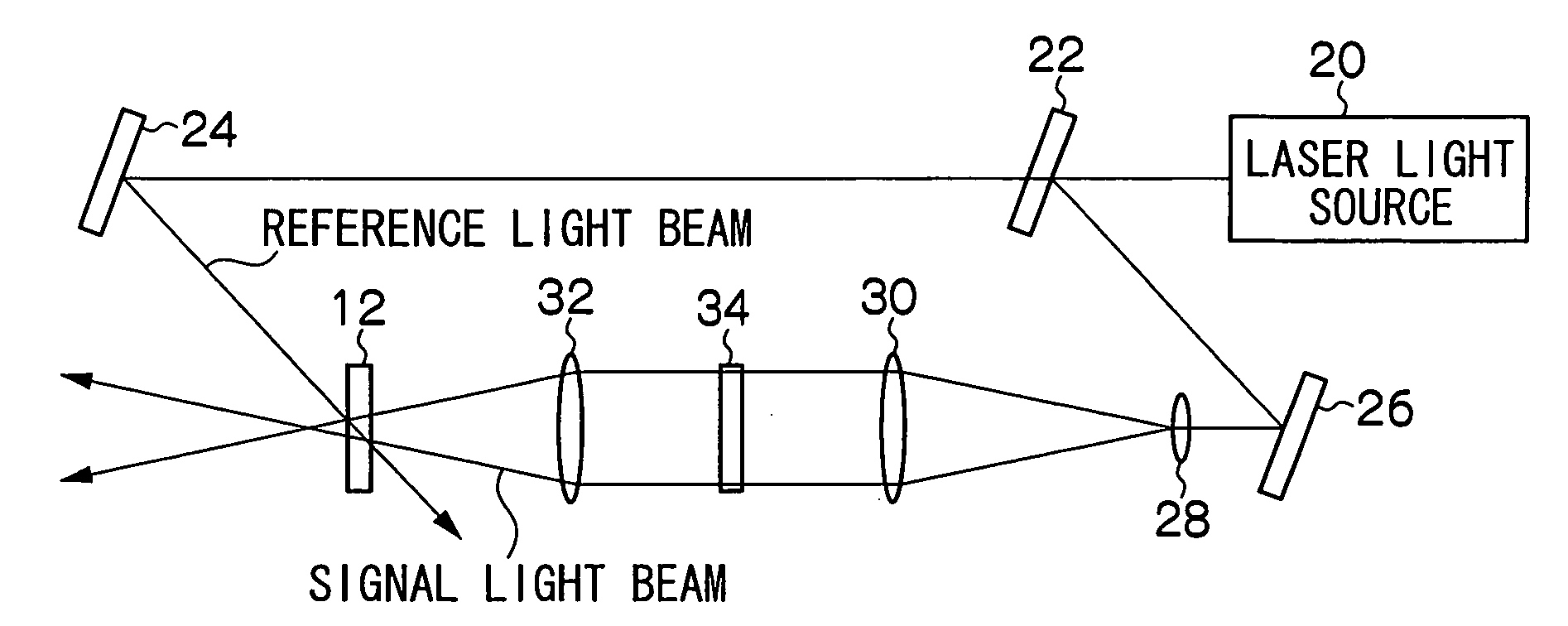
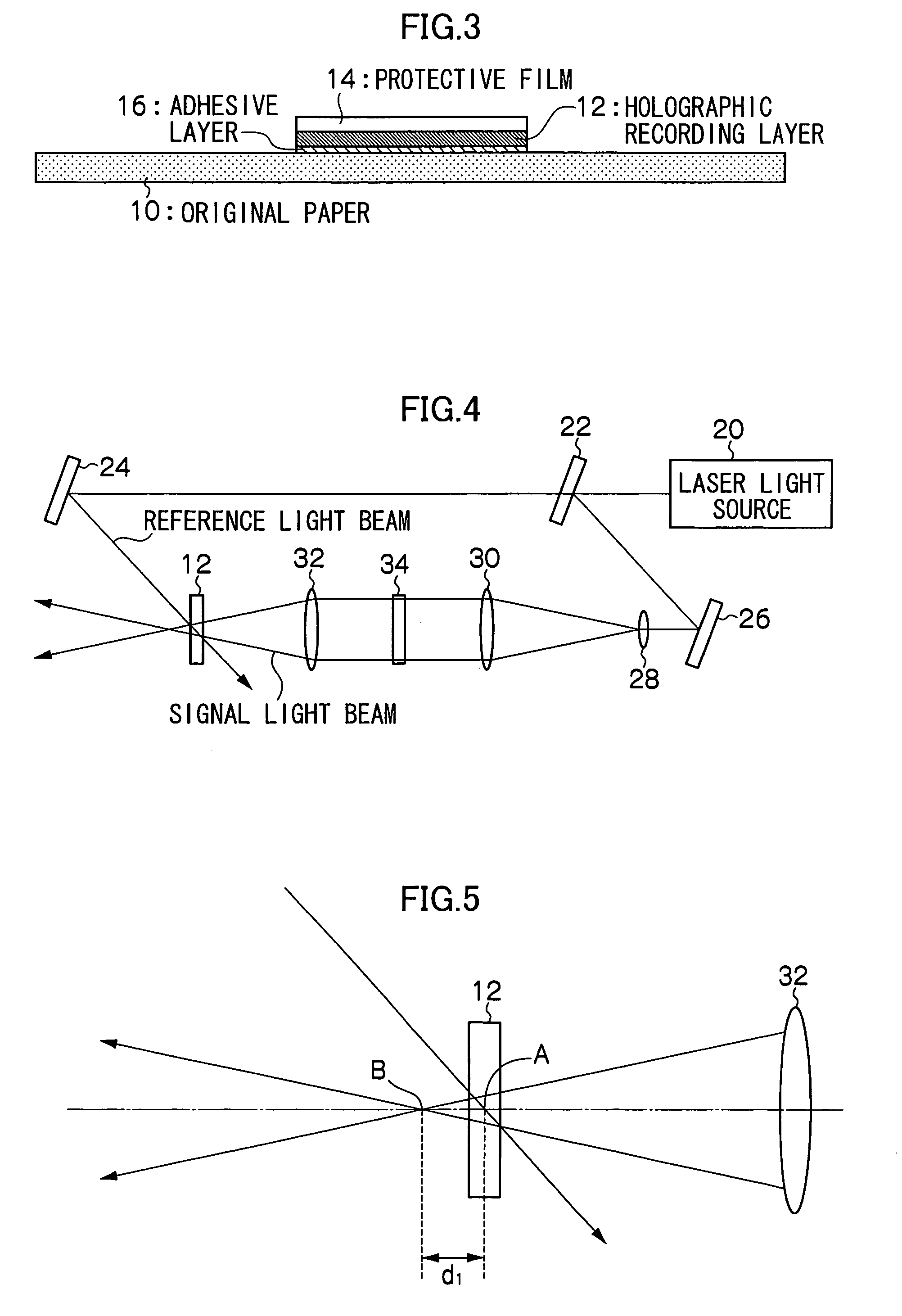
[0106] A reflection type hologram was recorded in the holographic recording layer with the recording apparatus shown in FIG. 5 under recording conditions shown below. FIG. 14 shows the arrangement of the sample (the holographic recording layer). FIG. 15 shows the recording data image.

(Hologram Recording Conditions)

[0107] Recording light source: Argon laser, wavelength of 514.5 nm [0108] Reference light beam: parallel light beam, power of 7 mW / cm2 [0109] Signal light beam: convergent light beam, power of 5 mW / cm2 [0110] Power ratio of signal light beam to reference light beam: 0.7:1 [011...

example 2

(EXAMPLE 2)

[0127] The commercial photopolymer film “OmniDex” (trademark, product of DuPont) having the layer structure shown below is cut into a small chip having a size of 10 mm by 10 mm, and the chip is used as the holographic recording layer.

(Layer Structure of Photopolymer Film)

[0128] Base film: thickness of 50 μm [0129] Photopolymer: thickness of 15 μm [0130] Cover film: thickness of 25 μm

[0131] Then, the cover film is peeled off, and the holographic recording layer is bonded onto a plastic card having a thickness of 760 μm.

[0132] A transmission type hologram is recorded in the holographic recording layer with the recording apparatus shown in FIG. 18 under the recording conditions shown below. FIG. 19 shows the arrangement of the sample (the holographic recording layer). FIG. 20 shows the recording data image.

(Holographic Recording Conditions)

[0133] Recording light source: Argon laser, wavelength of 514.5 nm [0134] Reference light beam: parallel light beam, power of 7 m...


PUM


Abstract

While Fourier transformation of a signal light beam is performed to perform recording during holographic recording so that a focal point is formed outside a holographic recording layer (defocus recording), an aperture is arranged on an outgoing side of the reproduced signal light beam (reproduction light beam), the reproduction light beam is focused at the aperture, and low-order components of a Fourier transform image of the reproduction light beam are selectively transmitted to detect only the transmitted light beam. Therefore, information recorded as the hologram in the holographic recording layer can be reproduced with high S / N ratio from the holographic recording layer added onto a support body, particularly onto a sheet member having non-optical quality such as paper and a plastic card.

Description

CROSS-REFERENCE TO RELATED APPLICATIONS [0001] This application claims priority under 35 USC 119 from Japanese Patent Application No. 2004-119058, the disclosure of which is incorporated by reference herein. BACKGROUND OF THE INVENTION [0002] 1. Field of the Invention [0003] The present invention relates to a method and apparatus for recording a hologram, a method and apparatus for reproducing the hologram, and an information retaining body, and particularly to a method and apparatus for recording a hologram, a method and apparatus for reproducing a hologram, and an information retaining body, in which information recorded as a hologram in a holographic recording layer is reproduced from the holographic recording layer added onto a support body, particularly onto a sheet member having a non-optical quality such as paper or a plastic card. [0004] 2. Description of the Related Art [0005] Recently, with development in information communication equipment, development of infrastructure, ...

Claims


Application Information

Patent Timeline
IPC IPC(8): B42D15/00B42D15/10G02B5/32G03H1/04G03H1/16G03H1/22G06K19/06
CPCG03H2001/0415G06K2019/0629G06K19/06046
Inventor HAYASHI, KAZUHIROKAWANO, KATSUNORIOGASAWARA, YASUHIROMINABE, JIROYASUDA, SHINYOSHIZAWA, HISAEMATSUI, NORIE
Owner FUJIFILM BUSINESS INNOVATION CORP
Learn More