Apparatus for preventing corrosion of contact

a technology of a contact and an apparatus, applied in the direction of contacts, percussive tools, manufacturing tools, etc., can solve the problems of increasing power consumption or generating noise, increasing loss in lsi, and current generating heat, so as to achieve the effect of easy noose judgment on the conta

Inactive Publication Date: 2005-10-20
FUJITSU GENERAL LTD
View PDF10 Cites 16 Cited by
  • Summary
  • Abstract
  • Description
  • Claims
  • Application Information

AI Technical Summary

Benefits of technology

[0011] The invention provides an apparatus for preventing corrosion of a contact, which can flow a corrosion-prevention current only when contact corrosion is detected. The apparatus also can perform a protect operation in an abnormal operation where the corrosion-prevention current is kept being flown.
[0017] With this configuration, when the comparator concludes that the contact is corroded, the corrosion-prevention current flows originally, since frequency of flowing of the corrosion-prevention current is low, it is expected that the corrosion-prevention current does not flow simultaneously into two or more contacts among the plural contacts. However, when the contact is in an abnormal state, the corrosion-prevention operations are performed with respect to two or more contacts independently. Therefore, the corrosion-prevention operations may overlap each other in terms of time. The anomaly determining section monitors corrosion-prevention current flowing through each signal line. When current flows through the switches in at least two of the signal lines of the preventing apparatuses simultaneously, the anomaly determining section concludes that the signal lines are abnormal. As a result, the anomaly judgment on the contact can be made easily.

Problems solved by technology

Thus, if the switch is opened and closed frequently, a pulse-like corrosion-prevention current may also be flown frequently even when the contact resistance of the contact does not increase, to thereby increase power consumption or generate noise.
In addition, since a corrosion-prevention current is a relatively large current, the current will generate heat when the current is frequently supplied from large-scale semiconductor integrated circuit (LSI).
If the current control apparatus for the contact is integrated into an LSI, since the corrosion-prevention current is kept being supplied, loss in the LSI increases, resulting in thermal destruction of the LSI.
Therefore, the corrosion-prevention current is kept being flown, thereby resulting in increasing loss or causing thermal destruction.

Method used


Image

  • Apparatus for preventing corrosion of contact
  • Apparatus for preventing corrosion of contact
  • Apparatus for preventing corrosion of contact

Examples


first embodiment

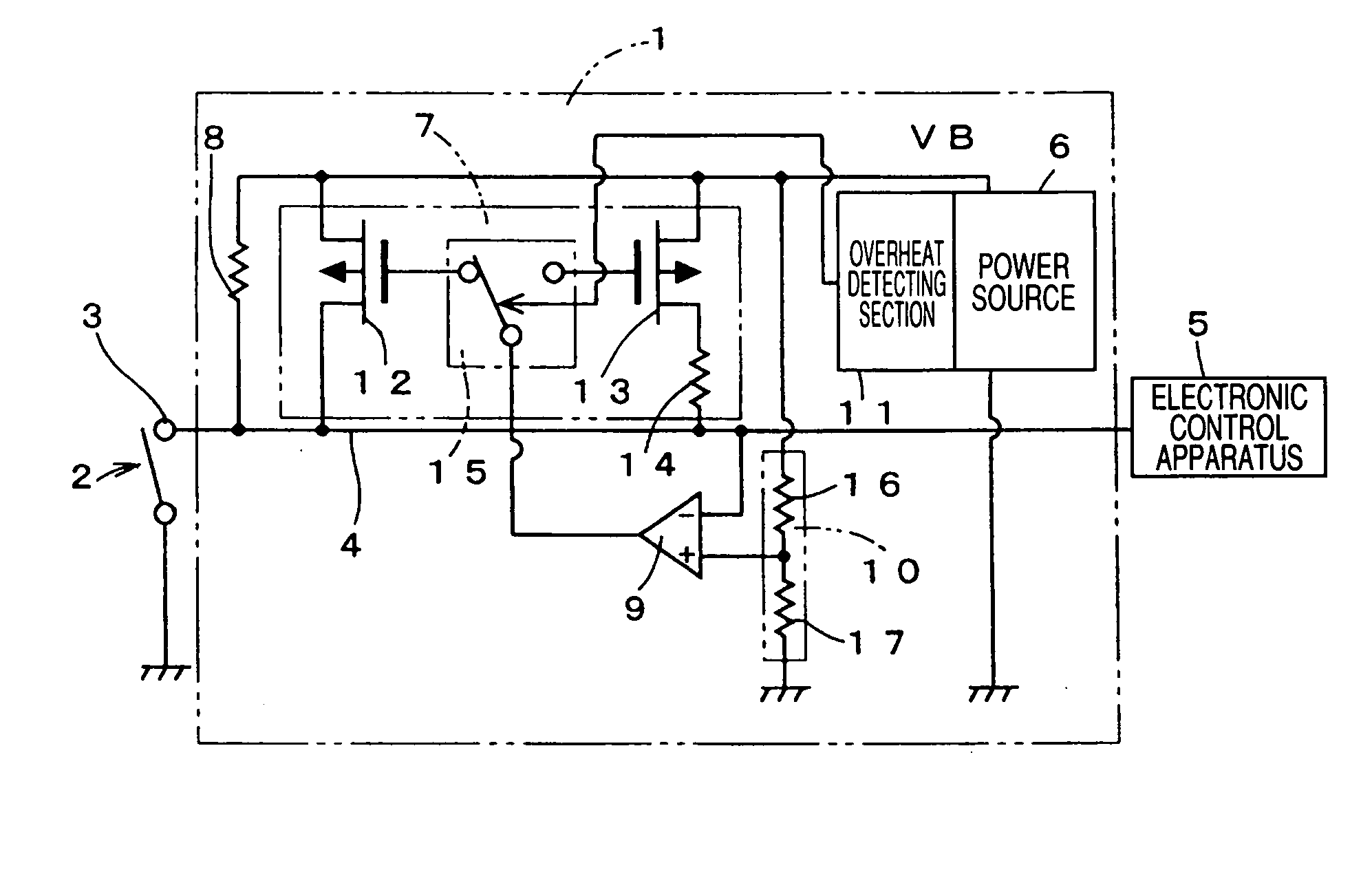
[0032]FIG. 1 illustrates a schematic electrical configuration of a apparatus 1 for preventing corrosion of a contact, according to the invention. The apparatus 1 has a function of preventing corrosion of a contact 3 of a switch 2. The contact 3 is connected via an input signal line 4 to an input side of the electronic control apparatus 5 at a subsequent stage. The contact 3 may be a contact of a connector. The apparatus 1 may be realized as a part of an LSI. A power source 6 generates a power-supply voltage for operating a logic circuit, from power supplied outside the LSI, and supplies it to inside of the LSI. The power-supply voltage for operating the logic circuit is, for example, 5V or 3.3V. This power source 6 is grounded at a low side thereof and outputs the power-source voltage from a high side thereof. The contact 3 is different in number and structure, depending on types and structures of the switch 2 or a connector. Moreover, the contact resistance of the contact 3 is an e...

third embodiment

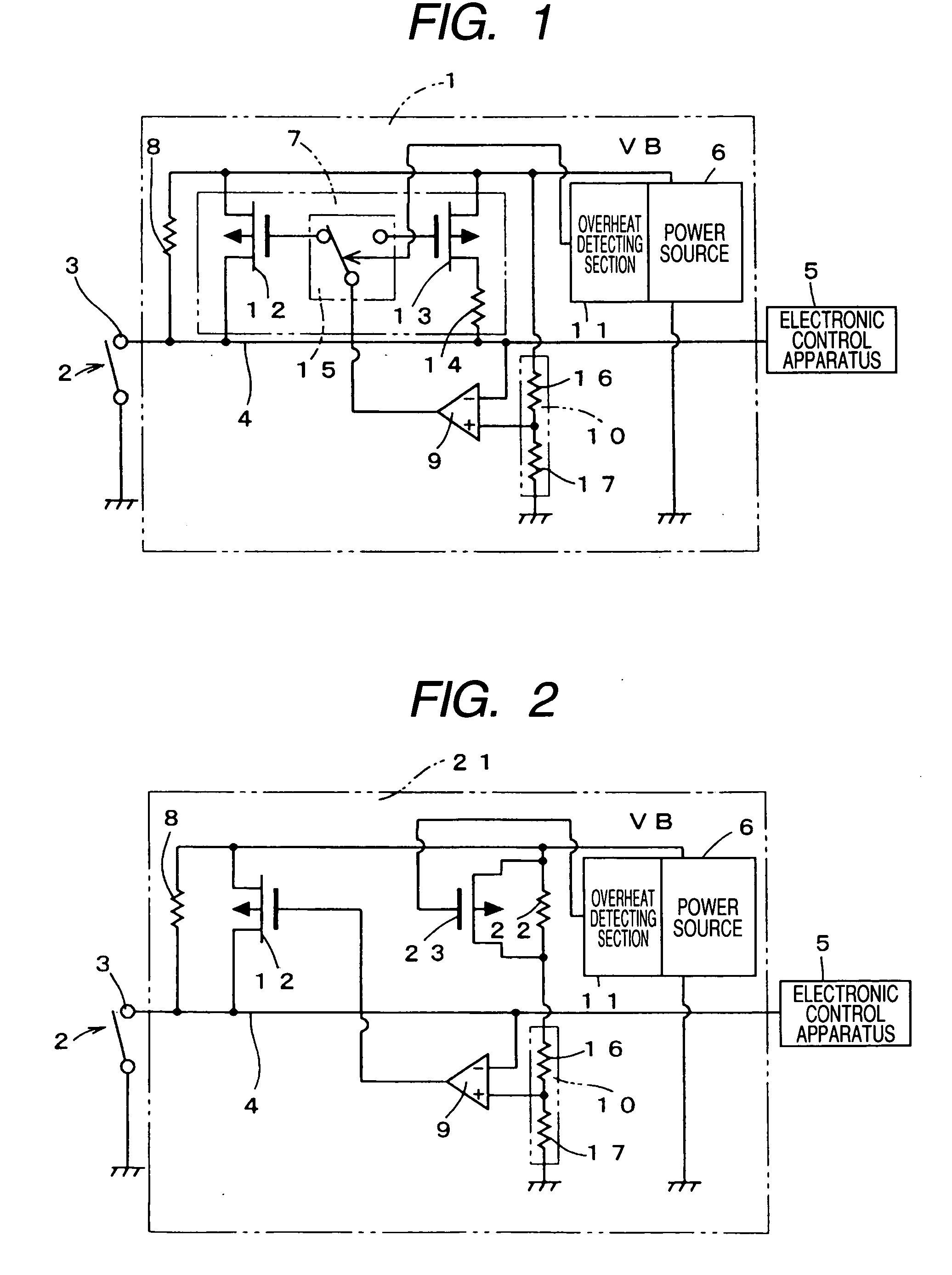
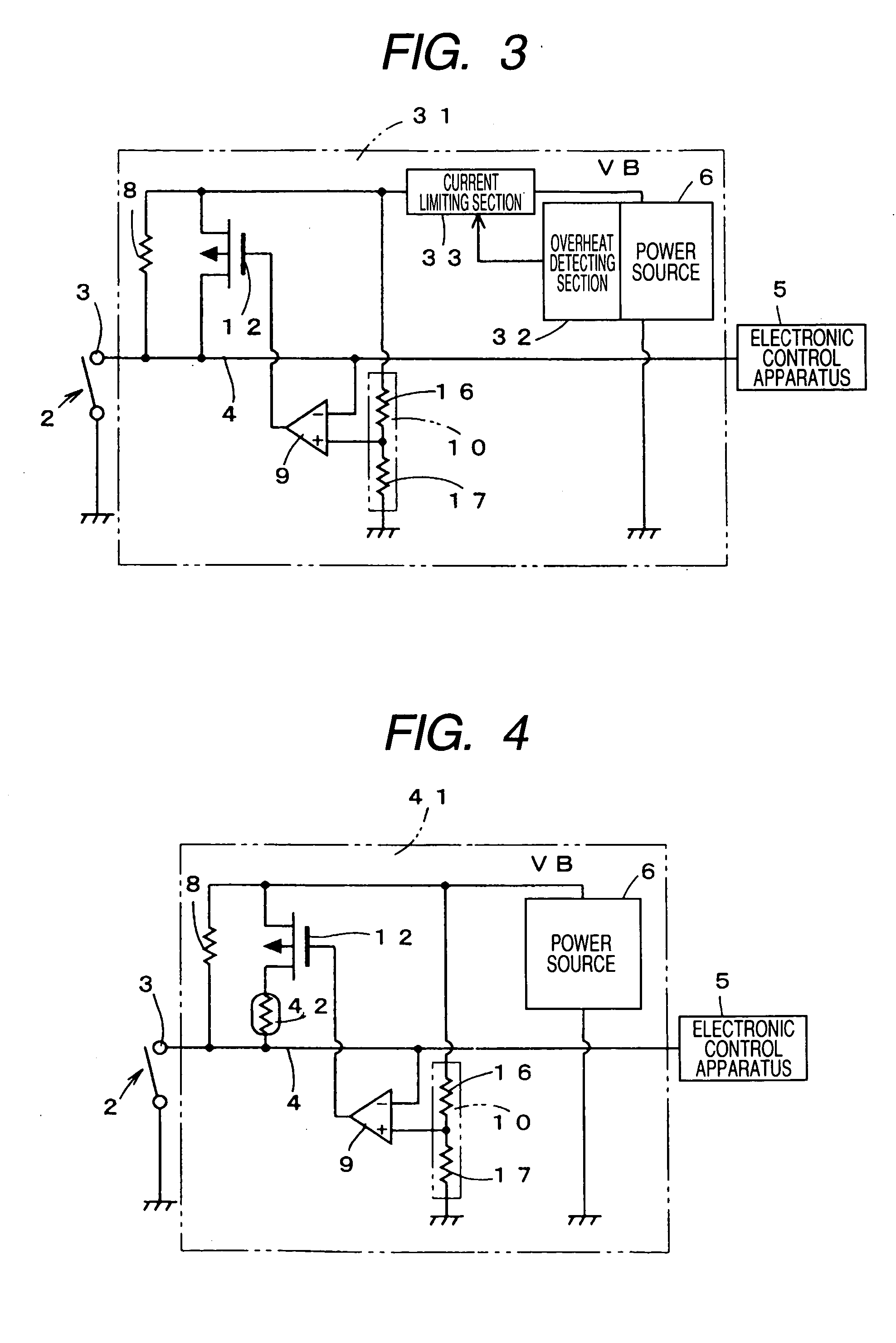
[0041]FIG. 3 illustrates a schematic electrical configuration of an apparatus 31 for preventing corrosion of a contact, in accordance with the invention. The contact apparatus 31 has an overheat detecting section 32 for detecting an overheat state of the power source 6, similar to the overheat detecting section 11 as shown in FIGS. 1 and 2. The apparatus 31 also has a current limiting section 33. The overheat detecting section 32 controls the current limiting section 33 disposed in a channel through which a current is supplied from the power source 6 to the switching element 12 serving as a low impedance section. The current limiting section 33 is implemented by a MOS transistor or a bipolar transistor. When the overheat state is not detected, the current limiting section 33 becomes a low impedance to reduce a limiting amount with respect to the current supply. On the other hand, when the overheat state is detected, the current limiting section 33 becomes a high impedance to limit t...

fourth embodiment

[0044]FIG. 4 illustrates a schematic electrical configuration of an apparatus 41 for preventing corrosion of a contact, in accordance with the invention. In the apparatus 41, a positive temperature characteristics resistance element 42 is connected in series to the switching element 12 serving as a low impedance section. Although the positive temperature characteristics resistance element 42 is disposed on the drain side of the P channel MOS transistor, which is the switching element 12, the positive temperature characteristic resistance element 42 may be disposed on the source side thereof or disposed at a position of the current limiting section 33 shown in FIG. 3.

[0045] The positive temperature characteristics resistance element 42 has positive temperature characteristics, which increase in resistance value according to elevation of temperature. In general, electric conductive materials such as a metal increase in resistance value according to elevation of temperature. For exampl...


PUM


Abstract

An apparatus for preventing a contact from being corroded includes a power source, a signal line connected to the contact, a resistance connected to the signal line, a switching section, a comparator, and an overheat detecting section. The switching section has a switch between the power source and the signal line. An impedance of the switch is smaller than that of the resistance when the switch is turned on. The comparator compares a potential of the signal line with a predetermined potential to determine as to whether or not the contact is corroded. The comparator outputs a driving signal when the comparator concludes that the contact is corroded. The overheat detecting section detects whether or not temperature of the apparatus exceeds a predetermined temperature. The overheat detecting section decreases current flowing through the switching section when the temperature of the apparatus exceeds the predetermined temperature.

Description

BACKGROUND OF THE INVENTION [0001] 1. Field of the Invention [0002] The present invention relates to an apparatus for preventing corrosion of a contact, which flows a large current to thereby destroy an oxide layer developed on the contact such as a switch or a connector and preventing the corrosion. [0003] 2. Description of the Related Art [0004] Inputs for various electronic controls have often been connected to a contact such as a switch or a connector. For example, in order to perform various types of control for an automobile, it is necessary to give input signals for control to many electronic control units (ECU). Input signals are given to an input terminal of an electronic control unit from a contact of a switch, which mechanically opens and closes, via a contact of a connector. [0005] Contacts such as a switch and a connector have been made with metal materials excellent in electric conduction so as to reduce contact resistance in electric connection. These contacts may inc...

Claims


Application Information

Patent Timeline
Patent Type & Authority Applications(United States)
IPC IPC(8): H01H1/60H01H9/54
CPCH01H1/605B25D1/12B25G3/04
Inventor KOMATSU, KAZUHIROFUJIMOTO, MASAHIKOOONISHI, KOUJIKIDO, KEISUKESAWADA, JUNICHI
Owner FUJITSU GENERAL LTD
Why Eureka
Try Eureka