Led fixing device of a pixel module and method for manufacturing the same

a technology of led fixing and pixel module, which is applied in the direction of lighting support devices, identification means, instruments, etc., can solve the problems of reducing the intensities of light of leds, reducing the life of leds, and generating heat due to the driving of leds, so as to prevent the lowering of light intensities

Inactive Publication Date: 2005-10-20
KOREA INST OF CIVIL ENG & BUILDING TECH +1
View PDF13 Cites 59 Cited by
  • Summary
  • Abstract
  • Description
  • Claims
  • Application Information

AI Technical Summary

Benefits of technology

[0024] In order to accomplish the third object of the present invention, an LED fixing device comprises: a fixing plate which is installed on the front side of a pixel module which comprises an LED driving circuit board into which an LED driving circuit is mounted and a plurality of LEDs which are arranged on the front side of the LED driving circuit board and flickered accor...

Problems solved by technology

The injection molding using a plastic material has an advantage in that the LED fixing device 20 is easily manufactured, but has a problem that the heat generated due to the driving of the LEDs cannot emit effectively in the air because of the low heat-emitting effect of the plastic of low heat conductivity.
Such a problem causes the deterioration of the LEDs generated by the superheat, and thus causes the problem that the intensities of light of the LEDs are lowered and the lives of the LEDs are shortened.
Further, the LED fixing device 20 using a plastic material, since the plastic material is a flam...

Method used


Image

  • Led fixing device of a pixel module and method for manufacturing the same
  • Led fixing device of a pixel module and method for manufacturing the same
  • Led fixing device of a pixel module and method for manufacturing the same

Examples


Embodiment Construction

[0035] Hereinafter, an LED fixing device and a method for manufacturing the LED fixing device according to preferred embodiments of the present invention will be explained with reference to attached drawings.

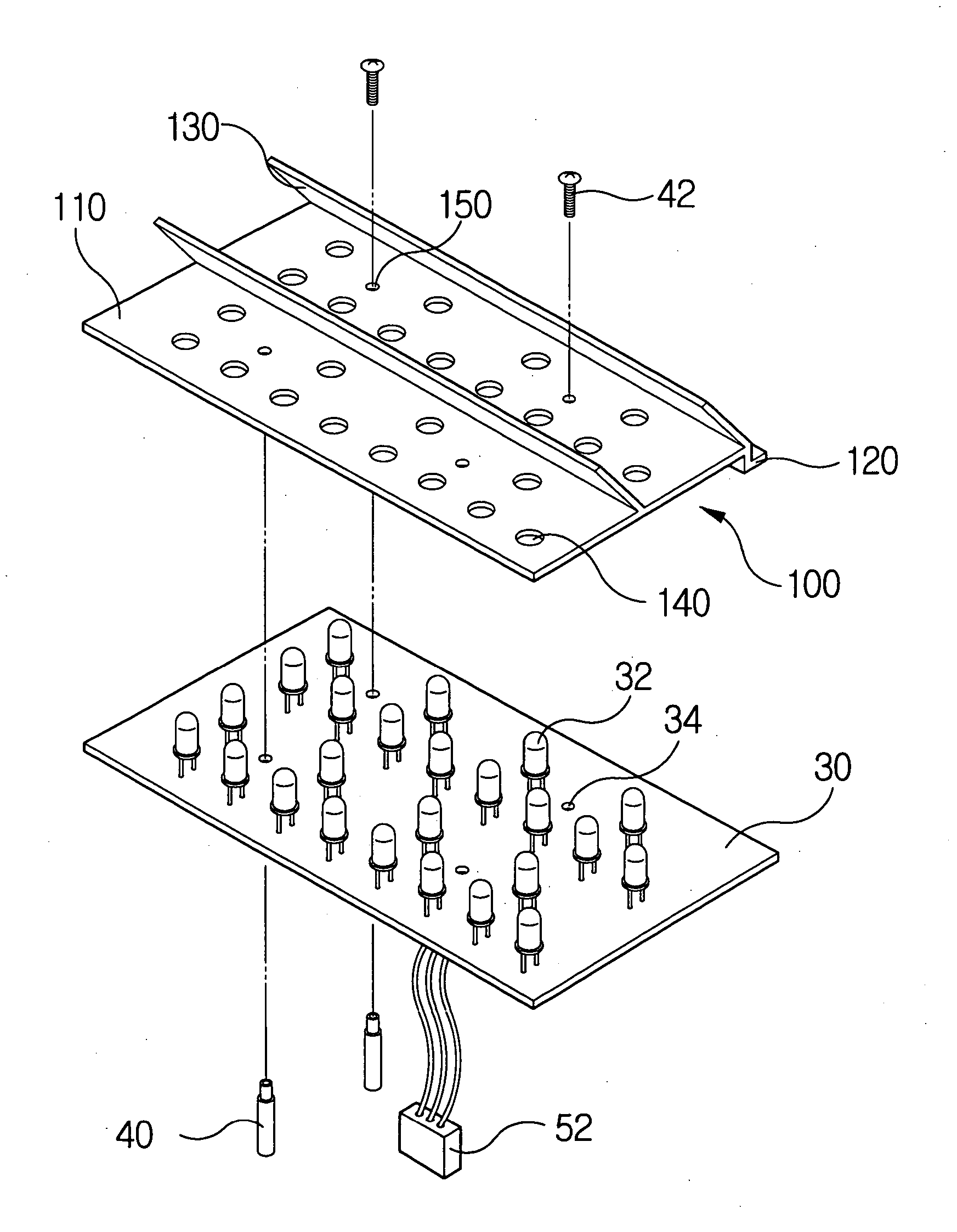
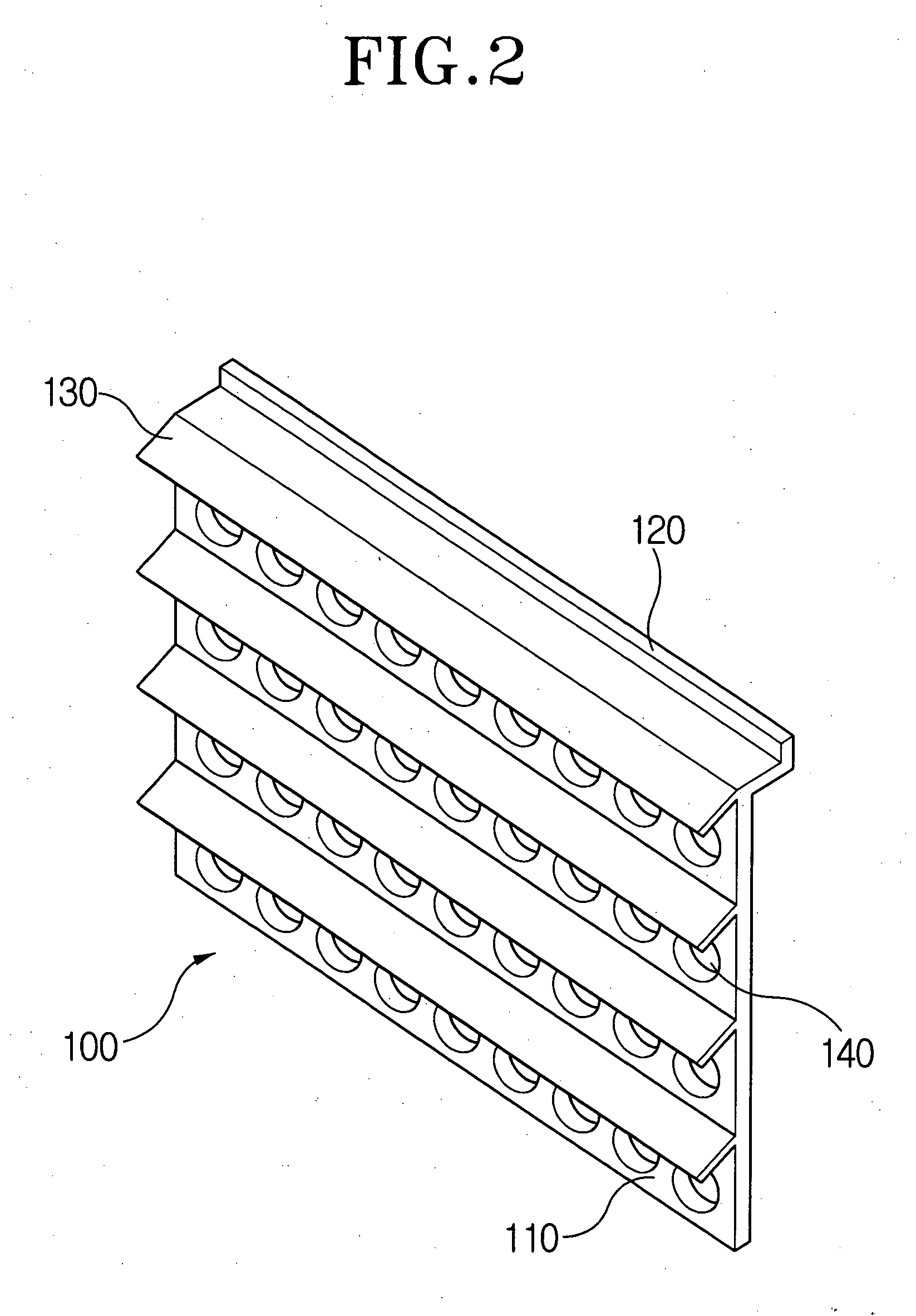
[0036] Referring to FIGS. 2 and 3, the LED fixing device 100 according to the present invention comprises a fixing plate 110 which is installed on the front side of a pixel module (not shown) and has a plurality of LED through-holes 140 to fix the LEDs, a water-leakage preventing jaw 120 which prevents the rainwater from being flowed into the interior of the pixel module in case of rain, and at least one intercepting plate 130 which is extended from the front side of the fixing plate 110 to prevent the lowering of intensities of light of LEDs which is generated due to the interference of the sunlight.

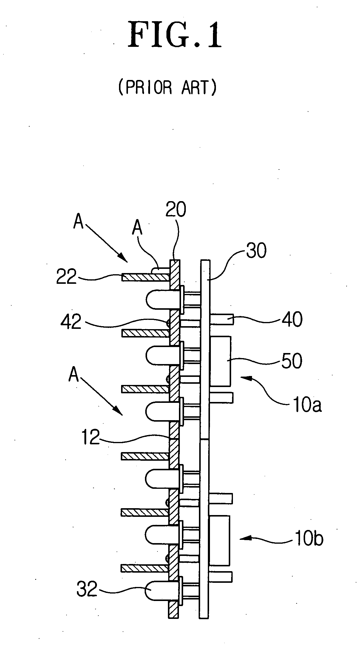
[0037] The pixel module comprises an LED driving circuit board into which an LED driving circuit is mounted and a plurality of LEDs which are arranged on the front side of the LED...


PUM


Abstract

An LED fixing device of a pixel module for a sign board which is installed on the front side of an LED panel of a road sigh board and which facilitates the downward flow of the rainwater and prevents the rainwater from being introduced into a pixel module and a method for manufacturing the LED fixing device. The LED fixing plate comprises a fixing plate which is installed on the front side of a pixel module which comprises an LED driving circuit board into which an LED driving circuit is mounted and a plurality of LEDs which are arranged on the front side of the LED driving circuit board and flickered according to electrical signals and which has a plurality of LED through-holes to fix the LEDs, and at least one intercepting plate which is extended from the front side of the fixing plate to preventing the lowering of intensities of light of LEDs which is generated due to the interference of the sunlight. The method for manufacturing the LED fixing plate comprises the steps of extruding the fixing plate and the intercepting plate through a cavity of a mold integrally and continuously, cutting the integrally and continuously extruded fixing plate and intercepting plate at intervals of a predetermined distance, and punching the LED through-holes for fixing the LEDs in the fixing plate.

Description

CROSS-REFERENCE TO RELATED APPLICATIONS [0001] This application claims benefit under 35 U.S.C. § 119 from Korean Patent Application Nos. 2004-22267 and 2004-51963, filed on Mar. 31 and Jul. 5, 2004, respectively, the entire contents of which are incorporated herein by reference. BACKGROUND OF THE INVENTION [0002] 1. Field of the Invention [0003] The present invention relates to an LED fixing device of a pixel module and a method for manufacturing the LED fixing device, and more particularly to an LED fixing device of a pixel module for a sign board which is installed on the front side of an LED panel of a road sign board and which facilitates the downward flow of the rainwater and prevents the rainwater from being introduced into a pixel module, and a method for manufacturing the LED fixing device. [0004] 2. Description of the Related Art [0005] Generally, an outdoor sign board device is widely used as a means for transferring letters and images by using one medium. The use of such ...

Claims


Application Information

Patent Timeline
IPC IPC(8): F21V21/00G09F9/33
CPCG09F9/33G09F27/008Y10S362/812Y10S362/80F21Y2105/001F21Y2105/10F21Y2115/10
Inventor KIM, CHUL YONGJUNG, JUN HWA
Owner KOREA INST OF CIVIL ENG & BUILDING TECH
Why Eureka
Try Eureka