Distributed voting system and method for land mobile radio system

a voting system and land mobile radio technology, applied in the field of radio systems, can solve the problems of reducing the service life of the rf transceiver, the weaker transmission of the mobile and portable transceiver, and the inability to provide useful, reliable communications. the effect of latency

Active Publication Date: 2005-10-20
EAGLE TECH LLC
View PDF5 Cites 104 Cited by
  • Summary
  • Abstract
  • Description
  • Claims
  • Application Information

AI Technical Summary

Benefits of technology

[0007] The present invention relates to a distributed Internet Protocol (IP) voting system and method for a Land Mobile Radio (LMR) system that overcomes the drawbacks of existing digital voting systems by doing away with the need for specialized voting equipment and synchronized data paths. In addition the present invention significantly reduces the latency introduced by the transfer and buffering of synchronous data and by the voter polling.

Problems solved by technology

However, the mobile and portable RF transceivers served by the receive-and-transmit site typically have considerably smaller ERPs because of power, size and cost considerations.
A portable or hand-held transceiver, having a few small nickel-cadmium battery cells as its power source, is even more restricted and may generate an RF transmission signal of only 1 watt or less.
The result is that while all the LMR mobile / portable transceivers within the service area can typically receive the strong transmissions from the receive-and-transmit site, the receive-and-transmit site may not receive the weaker transmissions from the mobile and portable transceivers or may receive the transmissions at signal strengths that are too low to provide useful, reliable communications.
They also introduce significant delays (also known as latency) into the transmission due to buffering required to ensure that the transmitter does not under run, i.e. does not begin transmission before all the necessary data has been received, and to ensure that all receiving sites have sufficient time to get their data to the voter.
The problems associated with this approach to digital voting include the significant investment in voting equipment, the need for synchronized data paths, the latency introduced into the transmission by the buffering during transfer of the synchronous data and the need for the voter to poll all receivers serially.

Method used


Image

  • Distributed voting system and method for land mobile radio system
  • Distributed voting system and method for land mobile radio system
  • Distributed voting system and method for land mobile radio system

Examples


Embodiment Construction

[0015] The present invention relates to an improved voting method and apparatus for use in Land Mobile Radio (LMR) systems that will now described in more detail.

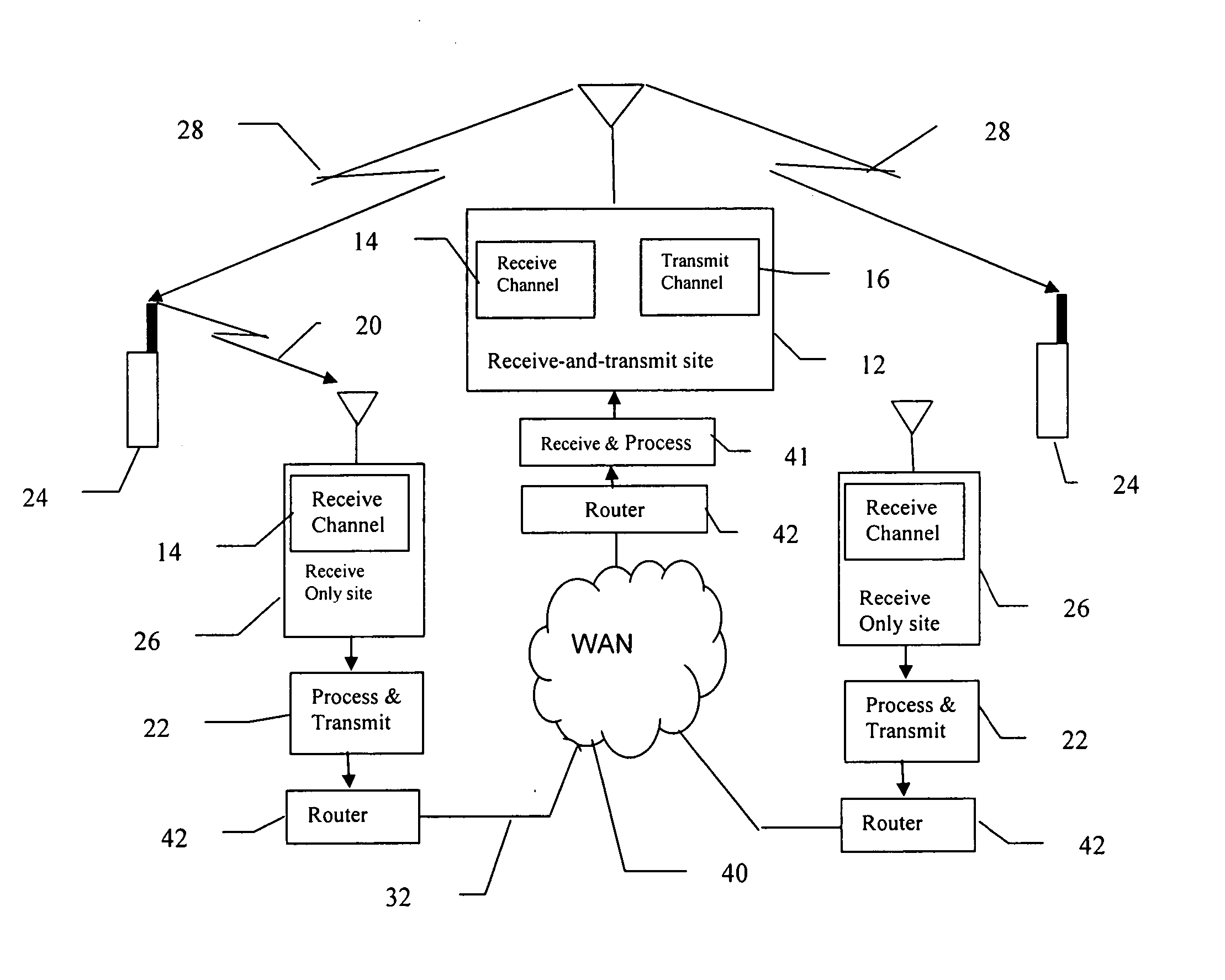
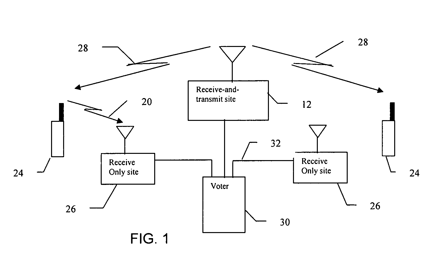
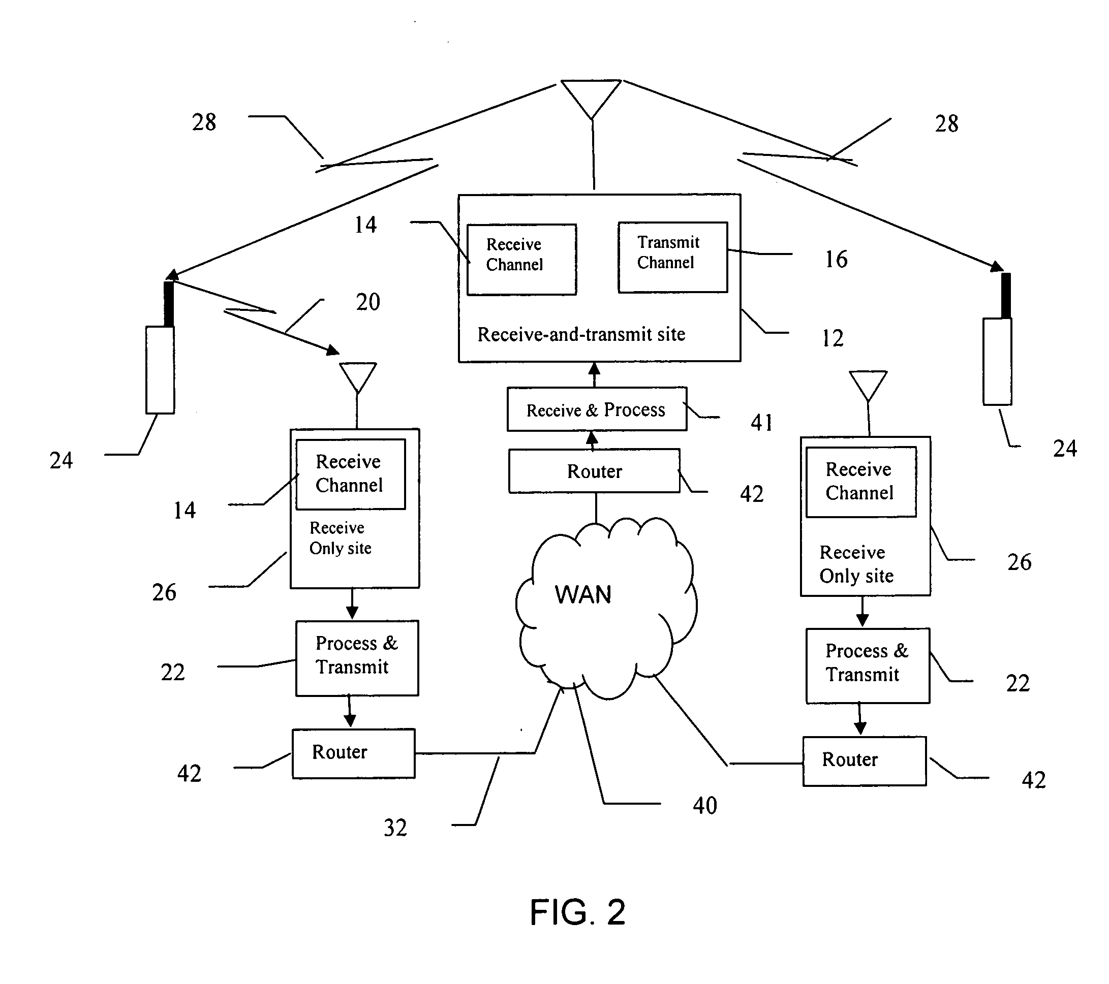
[0016] In the preferred embodiment of the present invention, each main transmitting site in the LMR system includes a receive-and-transmit site and associated receivers, transmitters and processing equipment. Each main transmitting site is also associated with one or more remote receiving sites, each of which includes a receive-only site and associated receivers and processing equipment. Communication between the main transmitting site and the remote sites includes an Internet Protocol (IP) enabled network. Each receiver in the LMR system that receives a transceiver transmission signal at a usable strength estimates the quality of the received transmission signal. The receiver combines its estimation of quality and the received transmission signal into a packet which is sent over a network to the main transmitting site ass...


PUM


Abstract

A distributed Internet Protocol (IP) voting system and method for use in Land Mobile Radio (LMR) Systems having a central send-and-receive site and one or more receive-only sites. In the distributed voting system, receive-only sites are directly linked to the control point using a network and associated packet transmission protocol. This may be a high-speed asynchronous data link such as a standard IP network link. Each remote site receiving digital data, calculates a bit error for that data. This error calculation is incorporated into the data header information. The data header information and data are placed in an IP packet and transmitted as a User Data Protocol (UDP) message to the control point. The control point selects the lowest bit rate data message, or the first control message, and retransmits it using a standard radio air interface protocol, such as the APCO Project 25 air interface protocol.

Description

FIELD OF THE INVENTION [0001] The present invention relates generally to the field of radio systems and more particularly to radio systems that select the most usable communications signal produced by one of a plurality of receivers. BACKGROUND OF THE INVENTION [0002] Modern Land Mobile Radio (LMR) communications systems typically have a number of geographically distributed receive-only sites associated with each receive-and-transmit site in the system. The need for these receive-only sites can be understood by considering a simple LMR system having a single receive-and-transmit site. The transmitter of this single receive-and-transmit site is designed to service a desired geographical area by an appropriate choice of the factors that contribute to its Effective Radiated Power (ERP). For instance, the receive-and-transmit site is typically located at a relatively high elevation, such as on the top of a hill, mountain or tall building, and has a relatively high-powered Radio Frequenc...

Claims


Application Information

Patent Timeline
Patent Type & Authority Applications(United States)
IPC IPC(8): H04B7/26H04B7/02H04B7/08H04L12/28H04W4/06H04W72/12H04W88/08
CPCH04B7/082H04B7/022
Inventor YOUNG, STEWART
Owner EAGLE TECH LLC
Why Eureka
Try Eureka