Live-cell biosensor polypeptides and methods of use

a biosensor and live cell technology, applied in biochemistry apparatus and processes, instruments, material analysis, etc., can solve the problems of difficult temporal resolution of specific cell cycle phases (e.g., mitosis) at the single cell level, and the difficulty of observing mitotic timing in statistically significant cell numbers,

Inactive Publication Date: 2005-10-20
THE BOARD OF TRUSTEES OF THE LELAND STANFORD JUNIOR UNIV
View PDF4 Cites 18 Cited by
  • Summary
  • Abstract
  • Description
  • Claims
  • Application Information

AI Technical Summary

Problems solved by technology

The other cell cycle phases are generally autonomously programmed events, which while normally insulated from extracellular growth signals, are still susceptible to the misregulation of proteins disrupting the checkpoints within the cell cycle phase.
Failures at this critical checkpoint lead to genetic instability, which is a hallmark of cancer and is correlated with aggressive tumor behavior (e.g., unregulated cellular proliferation).
However, since these methods provide snapshots of single cells that are usually synchronized (e.g., arrested at the same cell cycle phase prior to analysis), temporal resolution of specific cell cycle phases (e.g., mitosis) at the single cell level is difficult.
Nevertheless, observing mitotic timing in statistically significant cell numbers remains a challenge.

Method used


Image

  • Live-cell biosensor polypeptides and methods of use
  • Live-cell biosensor polypeptides and methods of use
  • Live-cell biosensor polypeptides and methods of use

Examples


example 1

Design of the Live-Cell Biosensor Polypeptide

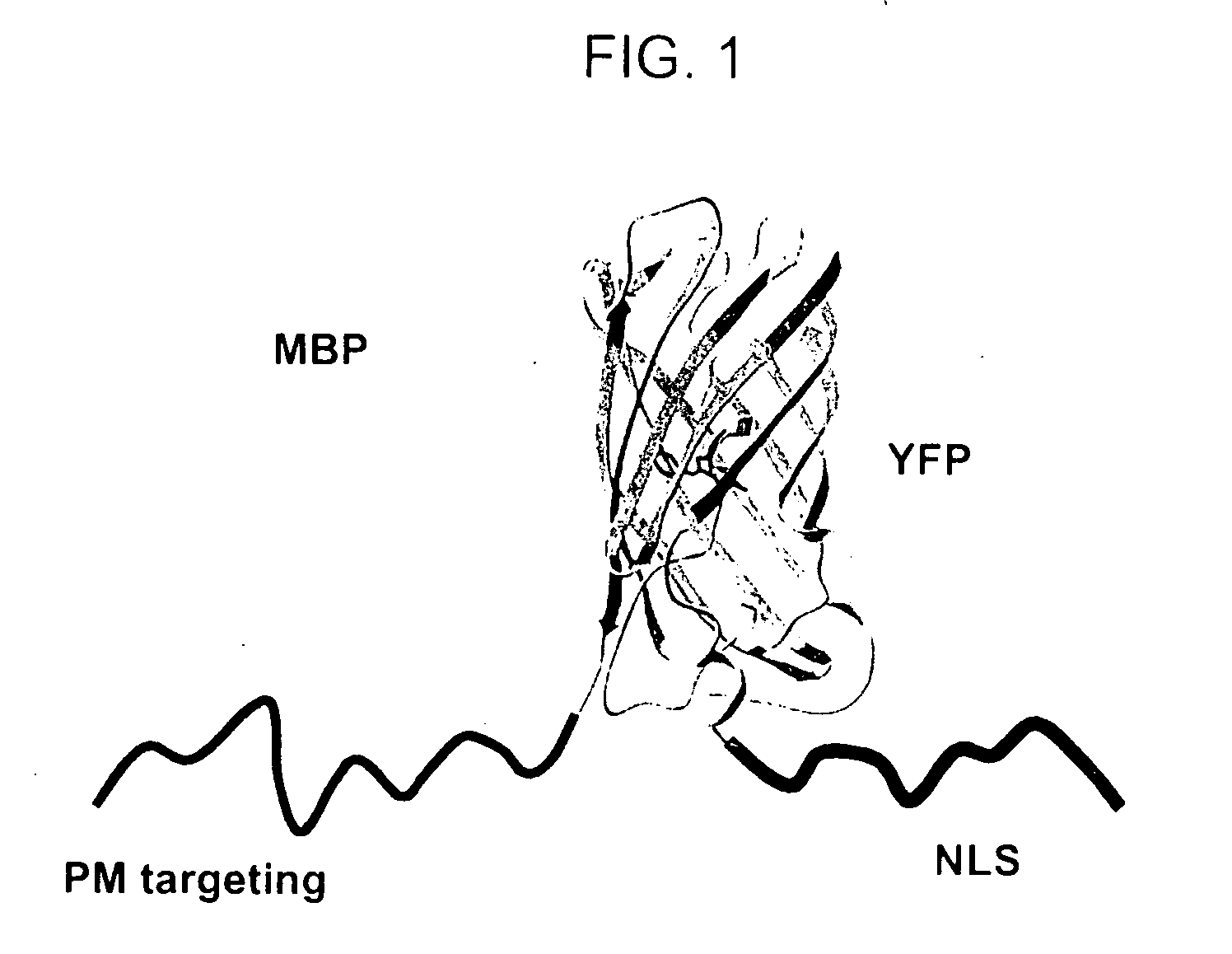
[0196] A mitosis biosensor polypeptide composed of three components—a reversible plasma membrane (PM) targeting domain, a fluorescent polypeptide, and a nuclear localization signal (NLS)—was produced as described above. In this example, the MBP included a reversible PM targeting domain fused to the NH2 terminus of a yellow fluorescent protein (EYFP), which was in turn fused to the NH2 terminus of a nuclear localization signal (EYFP-NLS, Clontech laboratories, Palo Alto Calif.) (FIG. 1).

[0197] A plasma membrane (PM) targeting motif based on polybasic residues was added at the N-terminus of an YFP-NLS (yellow fluorescent protein—nuclear localization signal) construct, as described in greater detail in the Examples section. The structure of YFP was adapted from Rekas et al., J. Biol. Chem. 50:573-578 (2002). It was hypothesized that a nuclear localization signal would ensure the biosensors localization to the nucleus during the G1, S, and ...

example 2

Location of the Biosensor Monitored by TIRF Microscopy

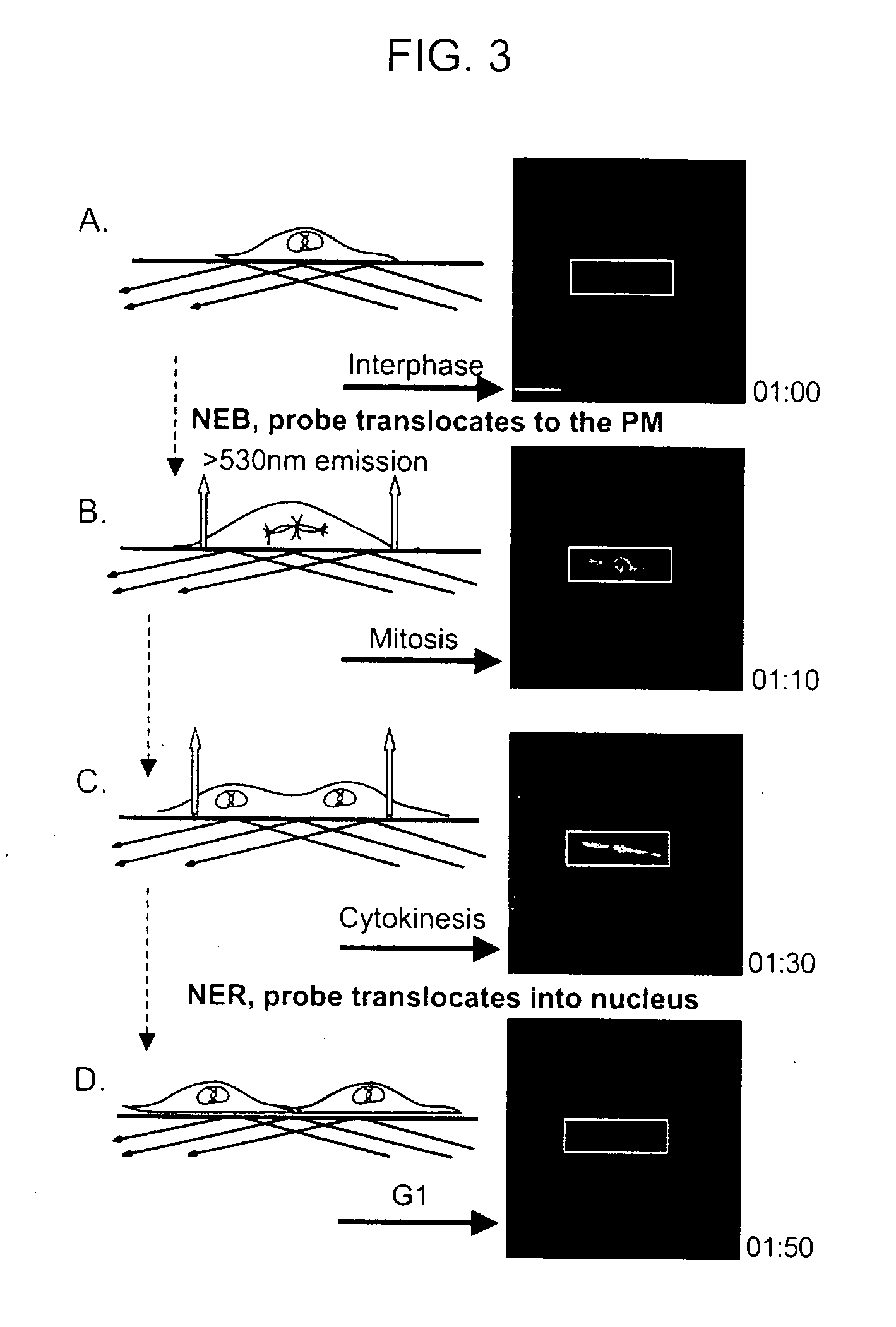
[0199] To determine if the change in fluorescence at the membrane could be monitored by TIRF microscopy, the same live cell imaging setup used in the confocal experiments above was adapted to a prism-based CFP / YFP TIRF system (FIG. 3). During interphase, no significant plasma membrane fluorescence was measured with TIRF, however, after NEB there was a large increase in plasma membrane fluorescence (FIG. 3, panels B and C). This fluorescence was maintained until the nuclear envelopes of the two daughter cells reformed and the biosensor translocated back into the nucleus. Translocation into the nucleus was paralleled by a rapid loss in plasma membrane fluorescence measured by TIRF microscopy (FIG. 3, panel D). Because the MBP is monitored by the less toxic TIRF microscopy, we were able take images at a rate of up to 2 images per minute, compared to every 5 minutes with epifluorescence imaging and 15 with confocal imaging, thus gre...

example 3

Monitoring Many Mitotic Events Using Wide Field TIRF

[0200] Based on the findings in the example above, a wide field TIRF microscope was used to monitor many mitotic events in the same experiment. FIG. 4 (panels A and B) shows two planes of a 5-hour TIRF experiment that was recorded through a 10× objective in which 70 cells proceeded through mitosis. In order to analyze these traces, the background was measured and subtracted from the fluorescence over time at each location where a mitotic event occurred. Typical examples of such individual traces are shown in FIG. 4, panel C. These results confirm that the time-period between nuclear envelope breakdown and reformation can indeed be measured from the TIRF signal, enabling an accurate quantification of the duration of mitosis.

Example 4

Detecting NEB, Anaphase, and NER with the Mitosis Biosensor

[0201] In 58 of the 70 cells (83%) that went through mitosis in the experiment above, a second smaller increase in plasma membrane fluoresce...


PUM

PropertyMeasurementUnit
TIRF time lapseaaaaaaaaaa
fluorescenceaaaaaaaaaa
fluorescence emission spectraaaaaaaaaaa

Abstract

Methods and compositions for determining the duration of a cell cycle phase of a mammalian cell, as well as identification of the cell cycle stage of fixed mammalian cells, are provided. In practicing the subject methods, at least one biosensor polypeptide that monitors a cell-cycle phase in a mammalian cell, such as mitosis, G1, S, or G2 phase, is used to determine the duration of a cell-cycle phase of a mammalian cell. Also provided are methods for identifying an agent (e.g., a gene product or small molecule compound) that modulates the duration of a cell-cycle phase of a mammalian cell, as well as kits and systems for practicing the subject methods.

Description

CROSS-REFERENCE TO RELATED APPLICATIONS [0001] This application claims the benefit of U.S. Provisional Application No. 60 / 541,297, filed Feb. 3, 2004, which application is incorporated herein by reference in its entirety.GOVERNMENT RIGHTS [0002] This invention was made with government support under federal grant no. 1018009-102 PAEFB awarded by National Institutes of Health. The United States Government may have certain rights in this invention.BACKGROUND OF THE INVENTION [0003] Progression through the cell cycle is the result of a highly regulated series of events in four defined phases. In the DNA synthesis phase (the S phase) the cell duplicates its DNA, which is followed by a gap phase (the G2 phase) in which the cell grows and prepares itself for mitosis. During mitosis (M phase) the cell divides its DNA and all of its contents into two separate daughter cells. Another gap phase (the G1 phase) follows mitosis and precedes the S phase. During the G1 phase cellular components are...

Claims


Application Information

Patent Timeline
Patent Type & Authority Applications(United States)
IPC IPC(8): C12Q1/68G01N33/50G01N33/53G01N33/567G01N33/58
CPCG01N33/5008G01N33/582G01N33/502
Inventor JONES, JOSHUAHAHN, ANGELAMEYER, TOBIAS
Owner THE BOARD OF TRUSTEES OF THE LELAND STANFORD JUNIOR UNIV
Why Eureka
Try Eureka