Vehicle speed control system

a control system and vehicle technology, applied in the direction of electrical control, process and machine control, etc., can solve the problems of insufficient advantage of feed-forward control, inability to match the test results obtained by the test driver with the test results, etc., to achieve low control accuracy and large weight

Active Publication Date: 2005-10-20
MEIDENSHA ELECTRIC MFG CO LTD
View PDF14 Cites 27 Cited by
  • Summary
  • Abstract
  • Description
  • Claims
  • Application Information

AI Technical Summary

Benefits of technology

[0004] However, these disclosed methods have encountered with a situation that an error of the engine characteristic data of the feed-forward circuit is amplified by the calculation of a transmission ratio, a differential ratio and a tire radius so as to unexpectedly lower the control accuracy. Therefore, these methods have executed a correcting calculation at the compensation circuit to compensate the lowering of the cont...

Problems solved by technology

However, these disclosed methods have encountered with a situation that an error of the engine characteristic data of the feed-forward circuit is amplified by the calculation of a transmission ratio, a differential ratio and a tire radius so as to unexpectedly lower the control accuracy.
As a result, the feedback control loop for the correction had ...

Method used


Image

  • Vehicle speed control system
  • Vehicle speed control system
  • Vehicle speed control system

Examples


first embodiment

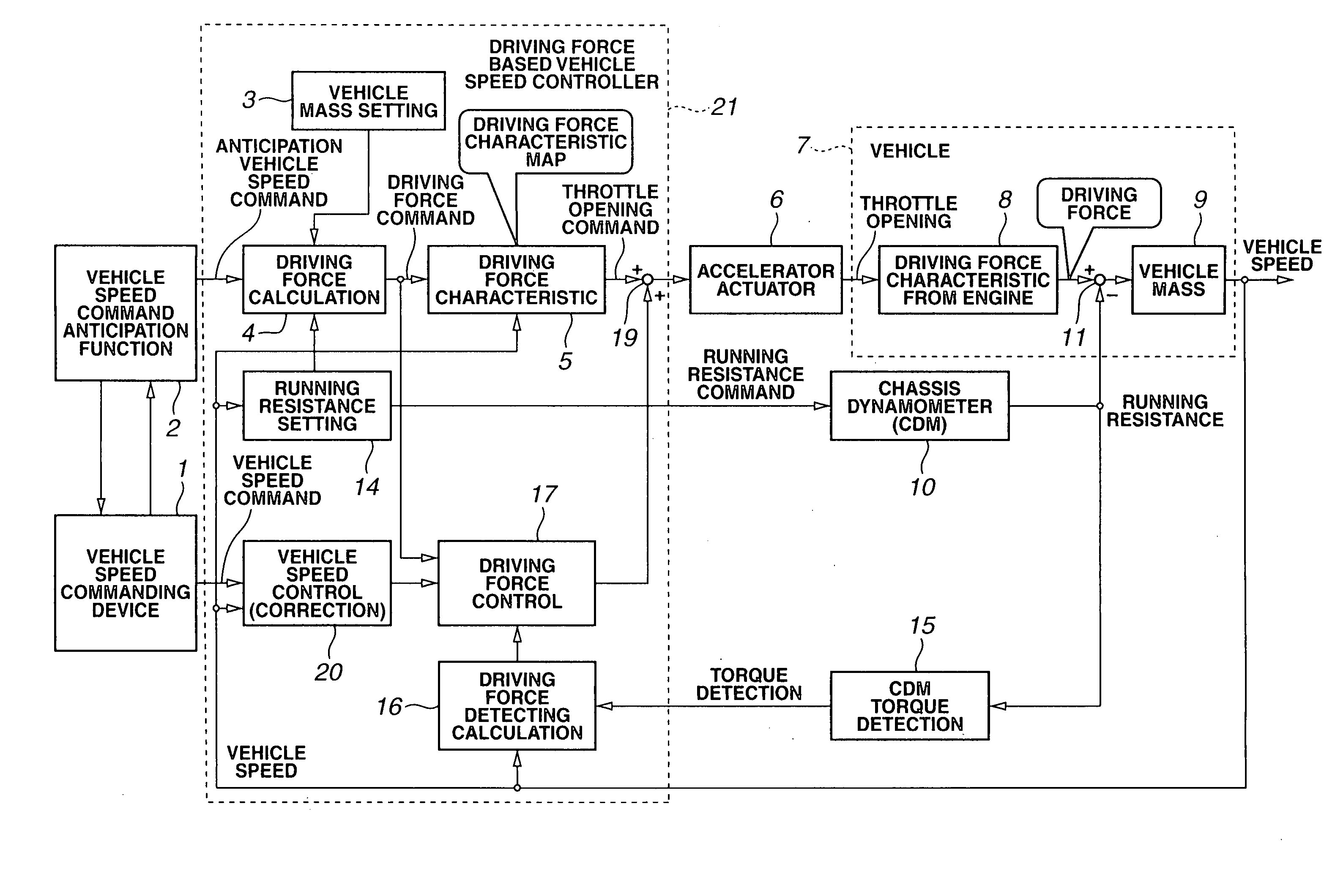
[0015] Referring to FIG. 1 there is discussed a first embodiment of a vehicle speed control system according to the present invention. The first embodiment is specifically arranged to execute a vehicle speed control based on a model that a driver manipulates an accelerator a vehicle. This vehicle speed control system is applied to a vehicle 7 tested on a chassis dynamometer (CDM) 10.

[0016]FIG. 1 is a block diagram showing a vehicle speed control system of a first embodiment according to the present invention. As shown in FIG. 1, the vehicle speed control system comprises a vehicle speed commanding device 1, a vehicle speed command anticipating section 2, a vehicle mass setting section 3, a driving force calculating section 4 and the driving force characterizing section 5.

[0017] The vehicle speed commanding device 1 outputs a vehicle speed command. The vehicle speed command anticipating section 2 calculates and outputs a anticipated vehicle speed command in response to the vehicle ...

second embodiment

[0029]FIG. 4 shows a conversion circuit for the driving force command and the detected vehicle speed used in the vehicle speed control system of a second embodiment according to the present invention. A driving force characteristic section 5a uses a driving torque characteristic map stored under a condition that the shift position of the transmission of the vehicle is fixed at second speed. A divider 44 receives the transmission ratio (T / M ratio) i2 at the second speed and a transmission ratio i1˜in at a present shift position, and divides the second-speed transmission ratio i2 by the present-speed transmission ratio i1˜in. The output of the divider 44 is inputted through a selector switch 45 to a multiplier 46. When the vehicle is equipped with a manual transmission, the selector switch 45 connects the divider 44 and the multiplier 46. When the vehicle is not equipped with the manual transmission, the select switch 45 release the divider 44 from the multiplier 46 and send a signal ...

third embodiment

[0033]FIG. 5 shows a braking timing automatic determining circuit of the vehicle speed control system employed in a third embodiment of the present invention. When the driving force command is minus (of requesting a braking), and the detected vehicle speed is higher than the sum of the vehicle speed command and 0.5 km / h, and the accelerator opening (throttle opening) is smaller than a play (an accelerator is fully closed), the brake on-command during the deceleration command is inputted to an S input terminal of an R-S flip-flop circuit 50 and the brake on-command is outputted from a Q output terminal of the R-S flip-flop circuit 50 so as to execute the brake control. Simultaneously an accelerator control on-command is outputted from a NOT logic circuit 51. In order to ensure a margin in the determination of the braking, 0.5 km / h was added to the vehicle speed command, and the sum of them is compared with the detected vehicle speed. Similarly, the other conditions for the determinat...


PUM


Abstract

A vehicle speed control system for controlling a vehicle on a chassis dynamometer is comprised of a controller which is arranged to receive a vehicle speed command, to obtain an anticipated vehicle speed command from the vehicle speed command taking account of a delay factor of a control system of the vehicle, to calculate a driving force a driving force command from the anticipated vehicle speed command, to obtain an accelerator opening command from a previously stored driving force characteristic map based on the driving force command and a detected vehicle speed, and to control an accelerator opening of the vehicle according to the accelerator opening command so as to adjust the detected vehicle at the vehicle speed command.

Description

BACKGROUND OF THE INVENTION [0001] The present invention relates to a vehicle speed control system applied to a vehicle driven on a chassis dynamometer. [0002] A known vehicle speed control system for a vehicle driven on a chassis dynamometer mainly by a feedback loop tends to be put in a situation that it is difficult to improve a responsibility of a vehicle seed control due to a response delay, a play and a hysteresis of the tested vehicle. In order to obtain a desired vehicle speed control result while overcoming the above situation, it was necessary for an expert engineer to perform an adjustment control using a relative long time period. [0003] In order to solve the above-discussed weakness of the feedback controlled vehicle speed control system, Japanese Published Patent Application No. 7-325019 discloses a feed-forward control method using an inverse function MG(S)−1 of a transfer function of a tested vehicle. Further in order to solve an error generated during a period of ob...

Claims


Application Information

Patent Timeline
IPC IPC(8): B60K31/00B60T7/12B60W30/14B60W40/12F02D29/02G01M17/007
CPCG01M17/0072A47K3/022A61H39/04A61H2205/12
Inventor MARUKI, TOSHIMITSU
Owner MEIDENSHA ELECTRIC MFG CO LTD
Why Eureka
Try Eureka