Drill cutting deoiling

a technology of drilling deoiling and cutting edge, which is applied in the direction of cleaning process and apparatus, cleaning using liquids, and borehole/well accessories, etc., can solve the problems of drilling fluid, environmental pollution, and disposed of oily cuttings,

Inactive Publication Date: 2005-10-27
HALLIBURTON ENERGY SERVICES INC
View PDF15 Cites 53 Cited by
  • Summary
  • Abstract
  • Description
  • Claims
  • Application Information

AI Technical Summary

Benefits of technology

[0016] A particular advantage of the present invention is the ability to recycle the solvent, either into the extraction system or possibly into hydrocarbon production operations.
[0017] Thus, the present invention comprises a combination of features and advantages which enable it to overcome various problems of prior devices. The various characteristics described above, as well as other features, will be readily apparent to those skilled in the art upon reading the following detailed description of the preferred embodiments of the invention, and by referring to the accompanying drawings.

Problems solved by technology

This method has the disadvantage that the drilling fluid, which may have further utility in the drilling process, is disposed of along with the drill cuttings.
Oily cuttings are environmentally difficult to dispose of.
Without such a system for cleaning contaminated cuttings, the use of oil muds is a very expensive proposition, since environmental regulations require that oil-contaminated cuttings be hauled from the remote drilling site to a treatment and disposal facility.
Such systems for burning off the oil from the cuttings suffer from drawbacks, such as only a partial cleaning of the cuttings caused by an unequal heating of the contaminated cuttings.
These conventional washing systems are less than desirable because they do not provide the necessary cleaning, the washing solution itself may pose a threat to the environment, and / or they require periodic shutting down of the system to allow for the settling of oily particles or for the removal of a highly contaminated washing solution which must be hauled to an approved onshore disposal site.
Such a complex separation system is undesirable not only from the standpoint of unit cost, but also high operating costs and problems associated with the use of volatile and / or environmentally dangerous solvents.

Method used


Image

  • Drill cutting deoiling
  • Drill cutting deoiling
  • Drill cutting deoiling

Examples


Embodiment Construction

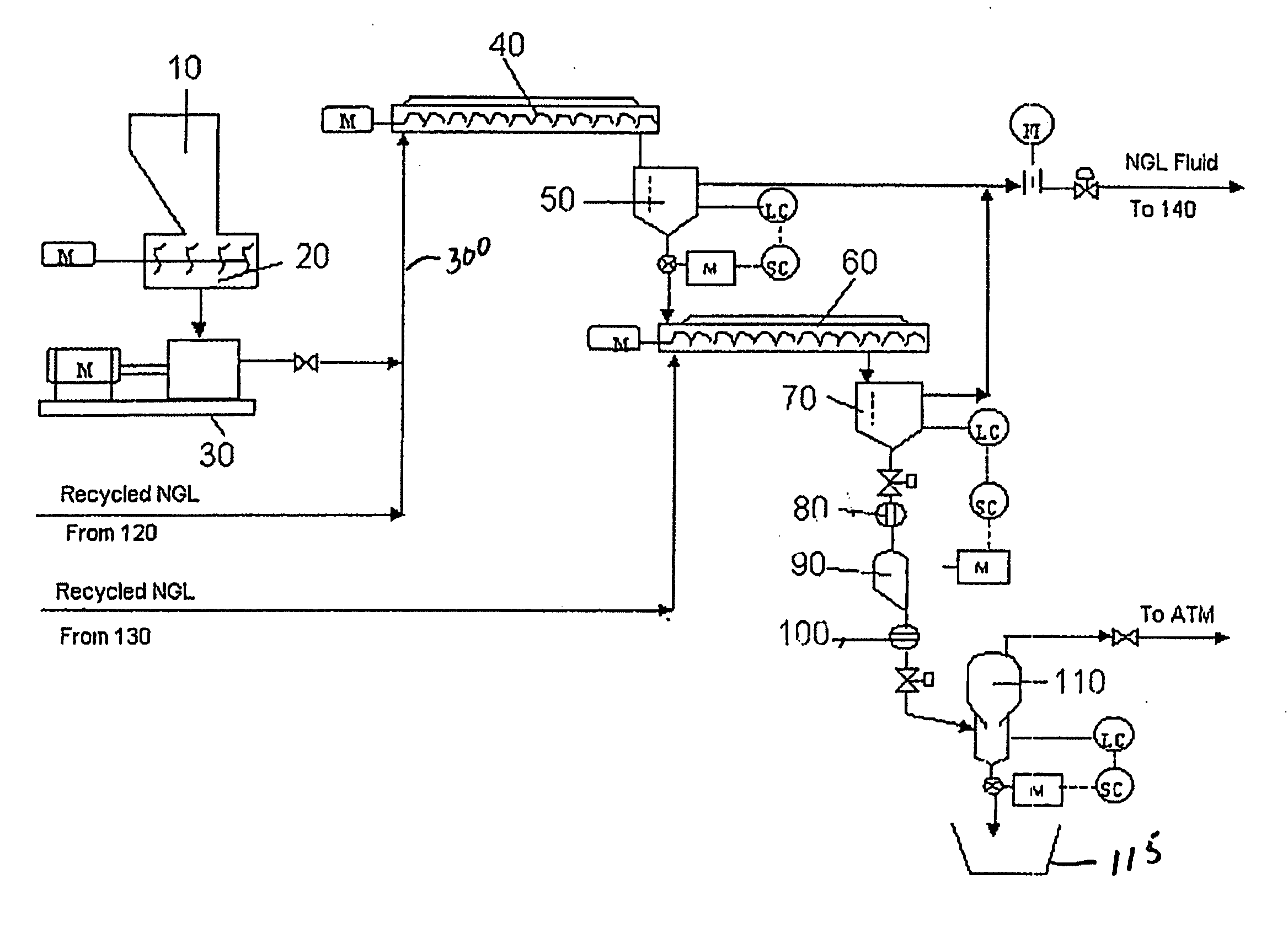
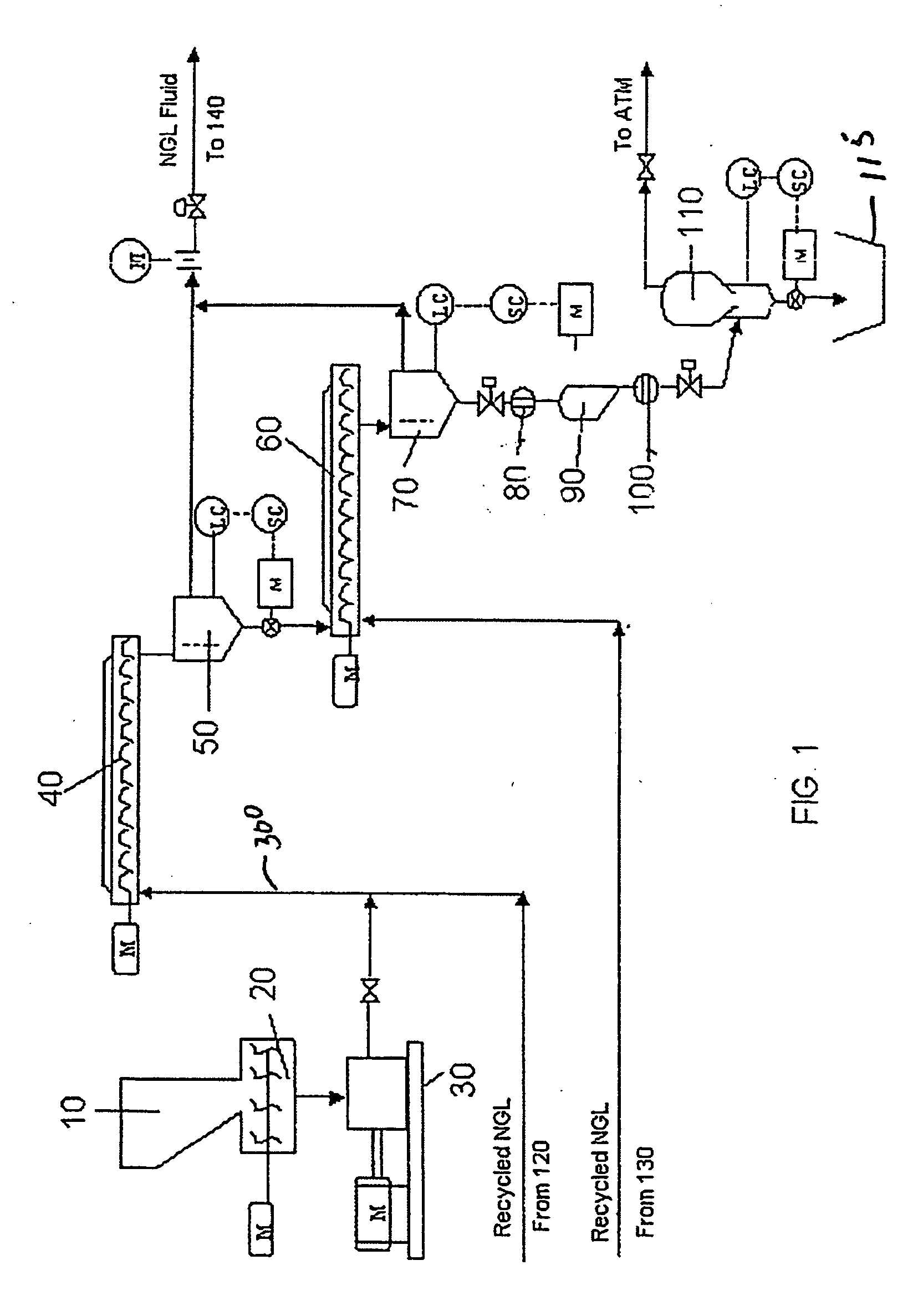
[0021] With reference to FIG. 1, an exemplary extraction system for deoiling drill cuttings includes feed hopper 10, sludge mulcher 20, sludge pump 30, primary extraction cell 40, primary separator 50, secondary extraction cell 60, secondary separator 70, solid hopper 90, degasser 110, and solvent recovery unit 120.

[0022] Still referring to FIG. 1, a used drilling fluid containing drill cuttings is fed into the feed hopper 10. The extraction process design is able to handle wide variations in feed composition and a wide variety of oils. The used drilling fluid typically contains 5-50 wt. % water, 5-50 wt. % oil, with the remaining wt. % being solids. Typically, the oil may be mineral oil, or diesel oil. Preferably, the extraction unit is capable of handling 200 bbls / day of drill cuttings. The drill cuttings typically contain about 50% by volume of oil-based drilling fluid adsorbed within the intergranular spaces or voids (pores) of the drill cuttings. The used drilling fluid may ha...


PUM

PropertyMeasurementUnit
wt. %aaaaaaaaaa
temperatureaaaaaaaaaa
pressureaaaaaaaaaa

Abstract

The present invention features a method and system for extraction of oil from drill cuttings. The extraction is carrying out by using a solvent. The extraction conditions preferably include a temperature and pressure each elevated above ambient and optionally to at least the critical point of the solvent. The cleaned drill cuttings may include not more than 1 wt. % oil.

Description

CROSS-REFERENCE TO RELATED APPLICATIONS [0001] Not Applicable. STATEMENT REGARDING FEDERALLY SPONSORED RESEARCH OR DEVELOPMENT [0002] Not Applicable. FIELD OF THE INVENTION [0003] The present invention relates generally to methods and apparatus for removing oil based drilling mud or like contaminants from drill cutting. More particularly, it concerns a system and method that uses a fluid as a solvent to extract the contaminants from the cuttings, and recycles the fluid through the system. Exemplary solvent fluids are light natural hydrocarbon solvents, such as natural gas liquids, propane and butane and other suitable well-born liquids and gases. BACKGROUND OF THE INVENTION [0004] It has been possible to efficiently remove oil and gas from the earth, both on land and offshore, for many years. The fluids that are removed may be processed on site as part of the producing operation. For example, natural gas is typically processed to separate natural gas liquids from pipeline quality me...

Claims


Application Information

Patent Timeline
Patent Type & Authority Applications(United States)
IPC IPC(8): E21B21/06E21B41/00
CPCE21B41/005E21B21/066
Inventor GOEL, RAVI K.FUNG, GEEDESAI, ANANTSHARMA, PUNEETSEATON, SIMONKIRSNER, JEFFNORMAN, LEWIS R.
Owner HALLIBURTON ENERGY SERVICES INC
Why Eureka
Try Eureka