
Controlled cooling of sputter targets

a technology of sputter targets and cooling fluids, applied in the field of sputter targets, can solve the problems of affecting the life cycle of sputter targets, degrading the uniformity of thin film deposition, and buildup of heat as an inherent side effect, so as to facilitate rapid flow or turbulent flow, increase the amount of heat dissipation, and accelerate the cooling fluid flow

Inactive Publication Date: 2005-10-27
HERAEUS INC
View PDF49 Cites 18 Cited by
  • Summary
  • Abstract
  • Description
  • Claims
  • Application Information

AI Technical Summary

Benefits of technology

[0008] In one aspect of the invention, a sputter target in which cooling rates are selectively controlled through surface area alteration is manufactured by generating a sputter surface and a backside surface obverse to the sputter surface. The backside surface includes at least a first textured region, where the first textured region aids in cooling a region of the sputter target adjacent to the first textured region, by effectuating heat dissipation.
[0023] In a fourth aspect, the present invention is a method for manufacturing a sputter target assembly in which cooling rates are selectively controlled through surface area alteration. The method includes the steps of generating a sputter surface on a sputter target, and generating a backside surface on a backing plate, where the backside surface includes at least a first textured region. The method also includes the step of bonding the sputter target and the backing plate together, so that the sputter surface is obverse to the backside surface. The first textured region aids in cooling a region of the sputter target assembly adjacent to the first textured region, by effectuating heat dissipation.

Problems solved by technology

The buildup of heat is an inherent side-effect of the sputtering process.
Too much heat can negatively affect the life-cycle of a sputter target, and degrade uniformity of thin-film deposition.

Method used


Image

  • Controlled cooling of sputter targets
  • Controlled cooling of sputter targets
  • Controlled cooling of sputter targets

Examples


Embodiment Construction

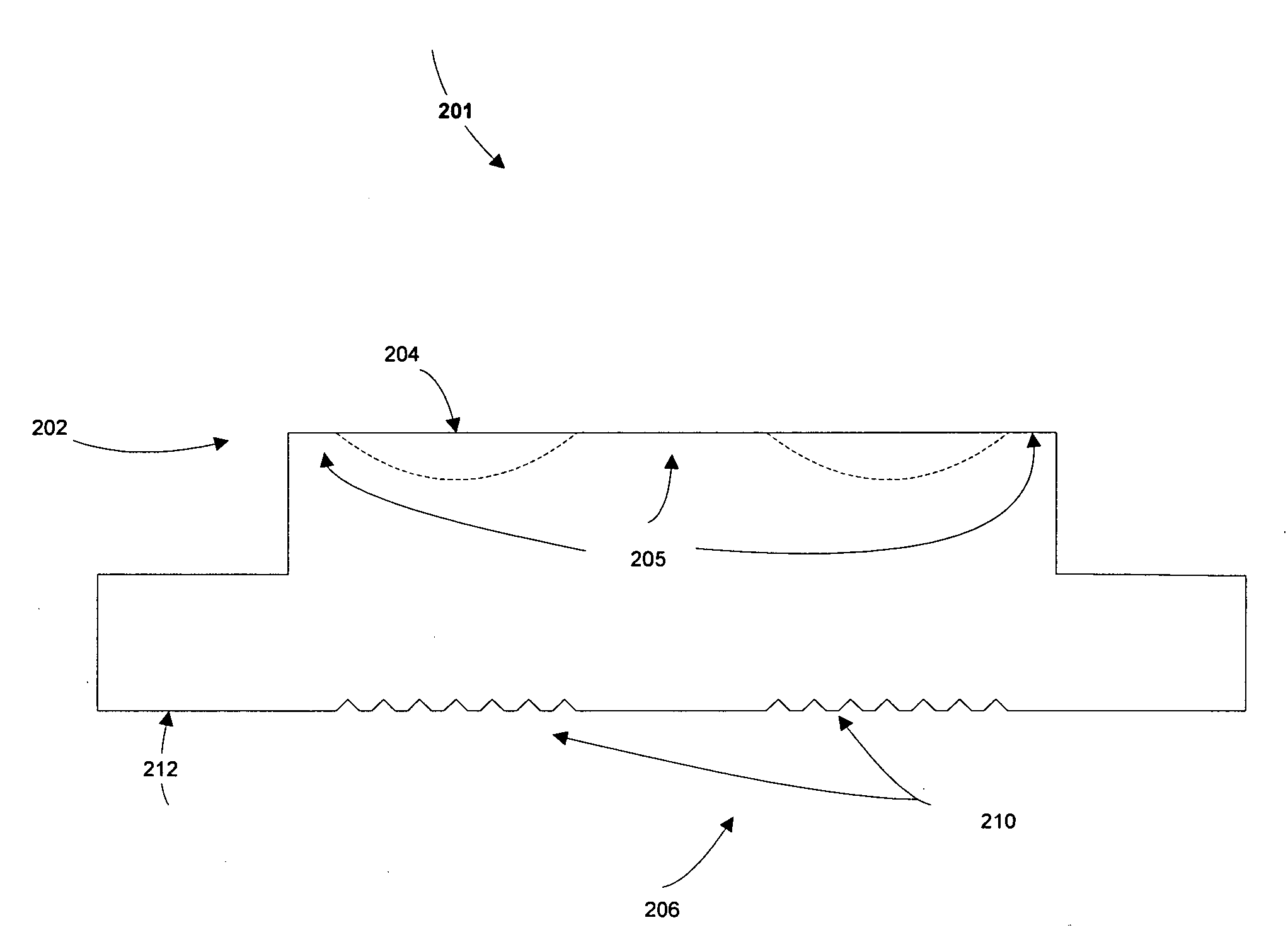
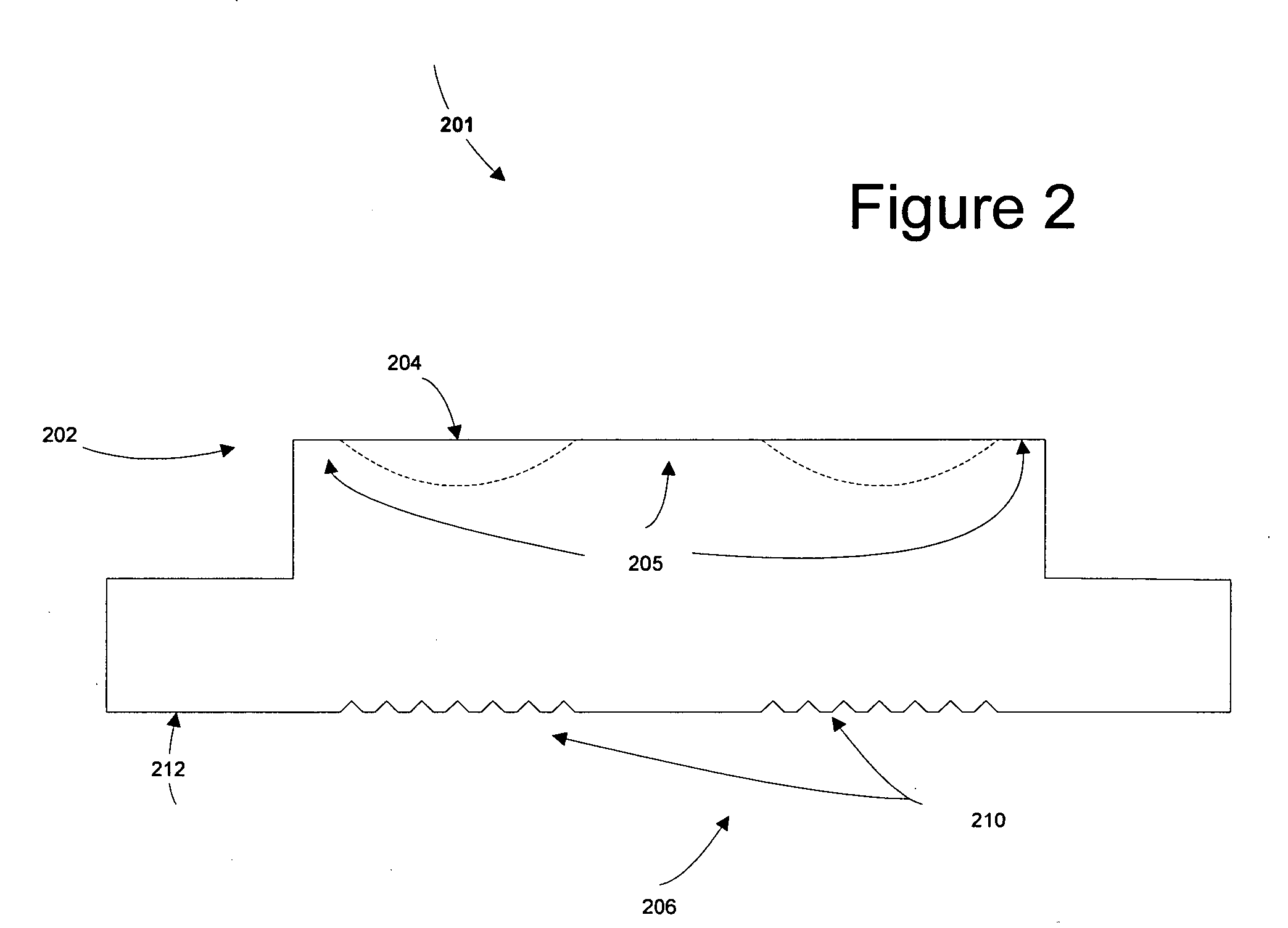
[0037] The present invention allows for improved control over the cooling of a sputter target and for extending the useful life of a sputter target, by controlling the cooling of the sputter target at selected areas through surface area alteration.

[0038]FIG. 2 depicts the external appearance of a sputter target according to the present invention. Briefly, the present invention relates to a sputter target in which cooling rates are selectively controlled through surface area alteration. The sputter target includes a sputter surface and a backside surface obverse to the sputter surface, where the backside surface further includes at least one textured region. The textured region aids in cooling a region of the sputter target adjacent to the textured region, by effectuating heat dissipation.

[0039] In more detail, sputter target 201 includes sputter surface 202, where sputter surface 202 further includes sputter area 204 for sputtering, and non-sputter areas 205. Sputter target 201 al...


PUM

PropertyMeasurementUnit
surface areaaaaaaaaaaa
areaaaaaaaaaaa
thicknessaaaaaaaaaa

Abstract

A method for manufacturing a sputter target in which cooling rates are selectively controlled, by generating a sputter surface and a backside surface obverse to the sputter surface. The backside surface includes at least a first textured region. The first textured region aids in cooling a region of the sputter target adjacent to the first textured region, by effectuating heat dissipation.

Description

FIELD OF THE INVENTION [0001] The present invention relates generally to the field of sputter targets and, more particularly, relates to controlled cooling of sputter targets through surface area alteration. DESCRIPTION OF THE RELATED ART [0002] The process of sputtering is widely used in a variety of fields to provide thin film material deposition of a precisely controlled thickness with an atomically smooth surface, for example to coat semiconductors and / or to form films on surfaces of magnetic recording media. In the sputtering process, a sputter target is positioned in a chamber filled with an inert gas atmosphere, and is exposed to an electric field to generate a plasma. Ions within this plasma collide with a surface of the sputter target causing the sputter target to emit atoms from the sputter target surface. The voltage difference between the sputter target and the substrate that is to be coated causes the emitted atoms to form the desired film on the surface of the substrat...

Claims


Application Information

Patent Timeline
Patent Type & Authority Applications(United States)
IPC IPC(8): C23C14/34H01L21/285
CPCC23C14/3407H01J37/3497H01J37/3423
Inventor CHENG, YUANDA R.KENNEDY, STEVEN ROGERRACINE, MICHAEL GENEDEODUTT, ANAND S.
Owner HERAEUS INC
Learn More