
CMOS-compatible integration of silicon-based optical devices with electronic devices

a technology of optical devices and electronic devices, applied in the direction of electrical equipment, semiconductor devices, radio frequency controlled devices, etc., can solve the problems of affecting the optical mode, the multi-mode nature of optical waveguides and electro-optic devices, and the difficulty in optimally using the free carrier-based electro-optic effect for manipulating light, so as to reduce the possibility of optical defects affecting optical performance and device yield

Inactive Publication Date: 2005-10-27
CISCO TECH INC
View PDF17 Cites 43 Cited by
  • Summary
  • Abstract
  • Description
  • Claims
  • Application Information

AI Technical Summary

Benefits of technology

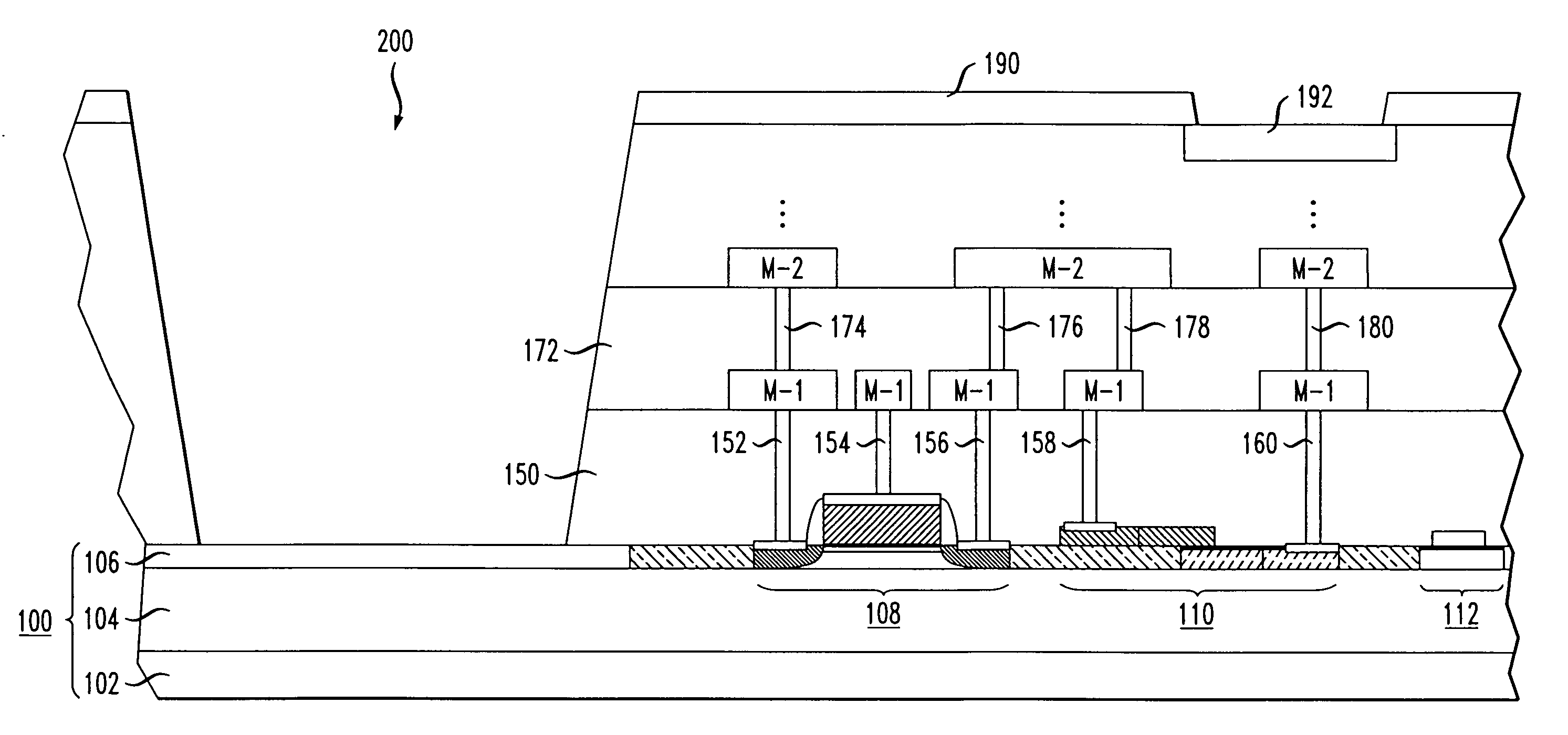
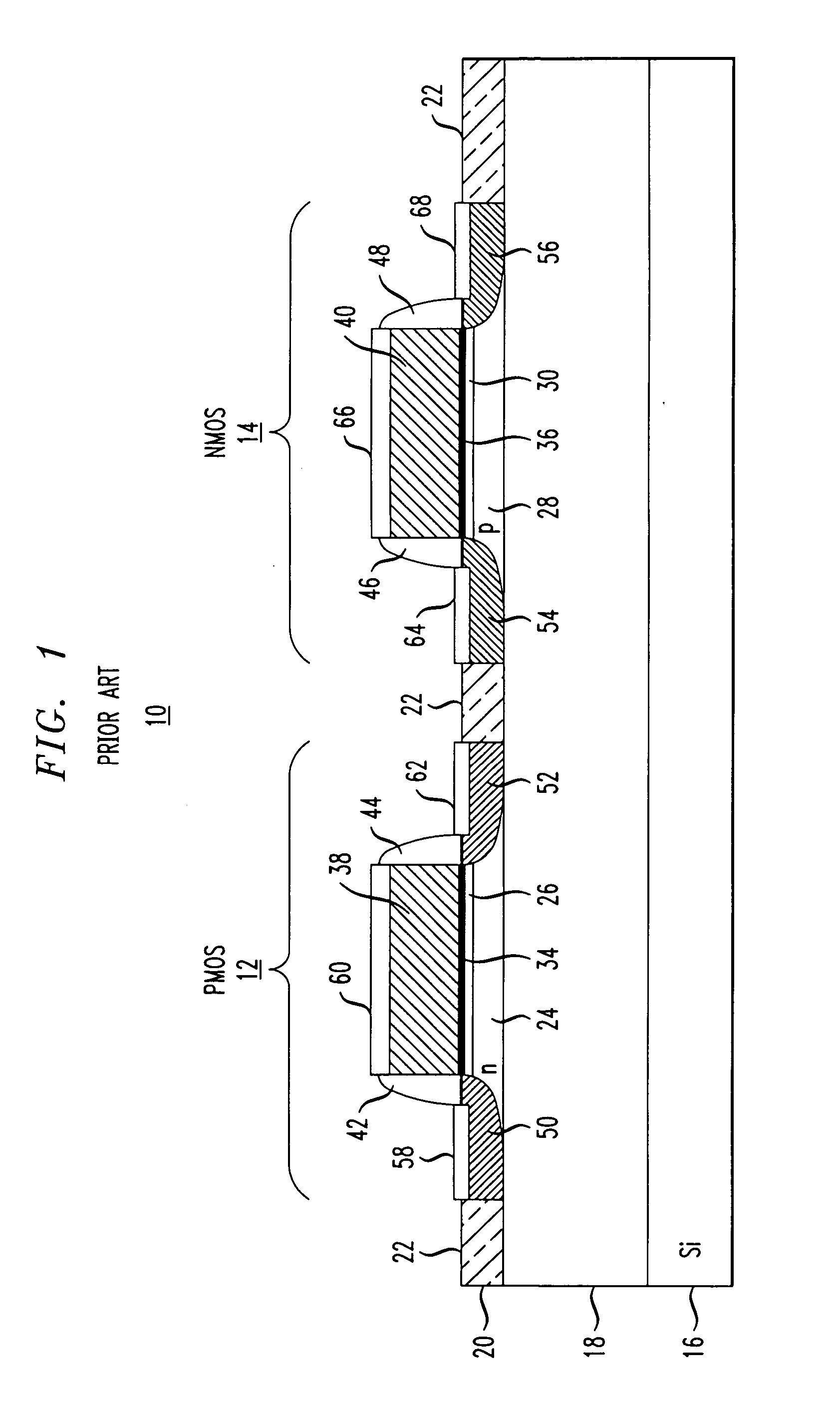
[0020] In accordance with the present invention, a wafer-scale testing is first performed to determine the quality of the SOI wafer before beginning any device fabrication, thus greatly reducing the possibility of optical defects affecting optical performance and device yield. Once the wafer has been “qualified” (from both an optical and electrical defect point of view), the various layers associated with the electrical, passive optical, and active electro-optical components are formed using conventional CMOS processing steps. In one embodiment of the present invention, the various regions of the electrical devices are formed simultaneously with the optical components.

Problems solved by technology

When properly designed and combined with the confinement of light in a silicon waveguide, an electronic device can modify the optical properties of the waveguide, thus affecting the optical mode.
Use of a thick SOI layer limits the optical waveguide and electro-optic devices to be multi-mode, making it difficult to optimally use the free carrier-based electro-optic effect for manipulation of light.
Further, due to the bulk-like silicon region formed in the thick SOI layer, the high speed and low power aspects of conventional SOI CMOS electronics cannot be achieved.
In addition, low resolution, non-conventional processes such as Deep reactive ion etching (RIE) are needed for definition of optical devices, and the resultant topology limits the use of conventional planarization and multi-level metallization processes, further limiting the realization of high performance electronics in combination with electro-optic devices on the same substrate.

Method used


Image

  • CMOS-compatible integration of silicon-based optical devices with electronic devices
  • CMOS-compatible integration of silicon-based optical devices with electronic devices
  • CMOS-compatible integration of silicon-based optical devices with electronic devices

Examples


Embodiment Construction

[0031] As mentioned above, the present invention discloses a CMOS-compatible processing scheme for the fabrication of planar optical and electro-optical devices with conventional CMOS electronic devices, without significantly altering the performance of high speed / low power CMOS transistors / circuits and with high yields.

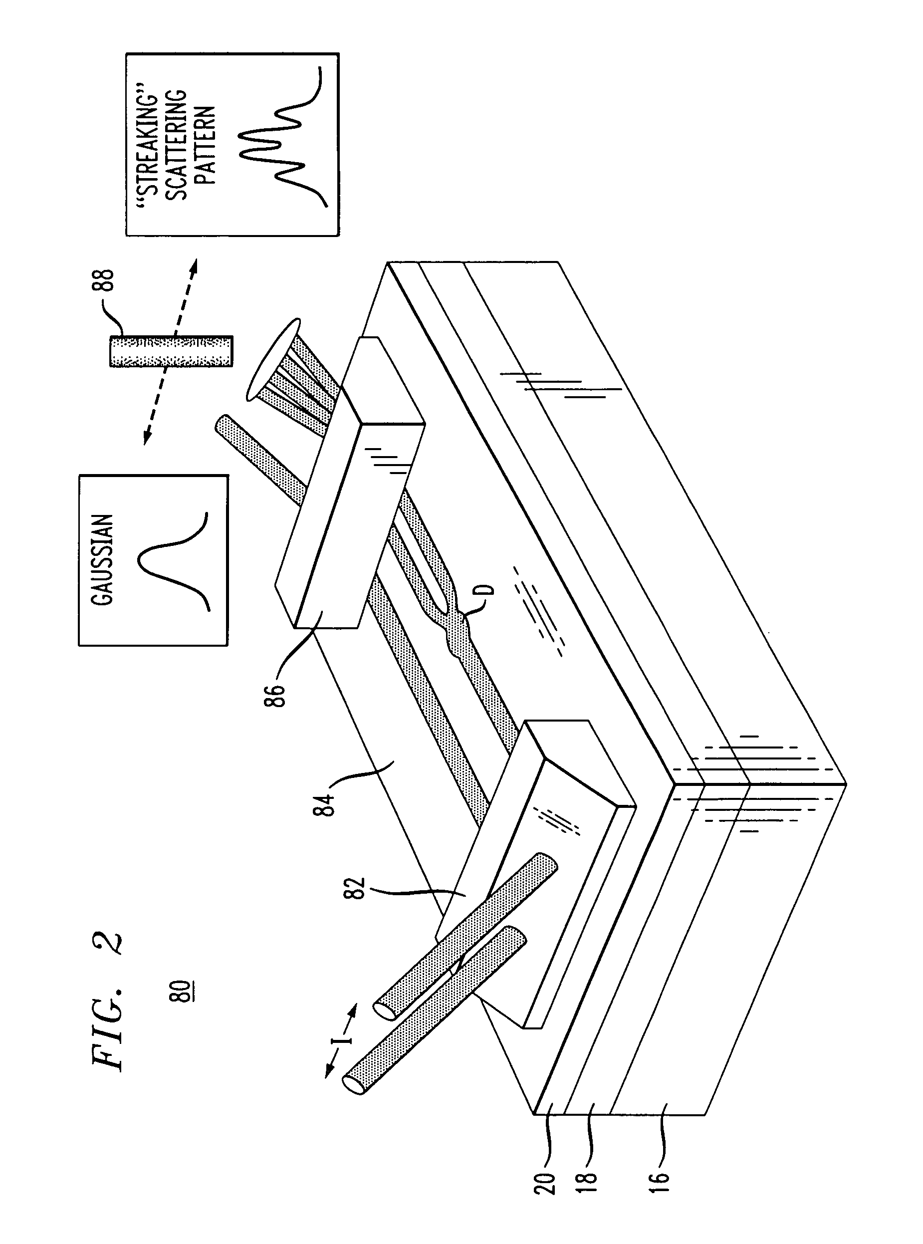
[0032] As optical and electro-optic devices have begun to be developed in a sub-micron thick SOI layer, a phenomena hereinafter referred to as “streaking” has been seen by the inventors in certain samples. In general terms, “streaking” occurs when a light beam propagating along a sub-micron SOI layer encounters an optical defect of some sort. The defect perturbs the local effective refractive index of the waveguide and results in scattering, and sometimes in an interference pattern that degrades the performance of the formed optical components.

[0033] The majority of defects that impact the optical performance of an SOI wafer (e.g., physical defects causing optical ...


PUM


Abstract

A conventional CMOS fabrication technique is used to integrate the formation of passive optical devices and active electro-optic devices with standard CMOS electrical devices on a common SOI structure. The electrical devices and optical devices share the same surface SOI layer (a relatively thin, single crystal silicon layer), with various required semiconductor layers then formed over the SOI layer. In some instances, a set of process steps may be used to simultaneously form regions in both electrical and optical devices. Advantageously, the same metallization process is used to provide electrical connections to the electrical devices and the active electro-optic devices.

Description

CROSS REFERENCE TO RELATED APPLICATION [0001] This application claims the benefit of Provisional Application Ser. No. 60 / 464,491, filed Apr. 21, 2003.TECHNICAL FIELD [0002] The present invention relates to conventional CMOS-compatible fabrication techniques for silicon-based optical devices and, more particularly, to the use of CMOS-compatible fabrication techniques that allows for the integration of conventional CMOS electronic devices with silicon-based passive optical devices and active electro-optic devices in the silicon-on-insulator (SOI) structure. BACKGROUND OF THE INVENTION [0003] Integrated circuits may be fabricated on silicon-on-insulator (SOI) substrates (as compared with bulk silicon substrates) to achieve higher device speeds and / or lower power dissipation. The SOI structure comprises a silicon substrate, a buried dielectric layer (for example, silicon dioxide) and a relatively thin (e.g., sub-micron) single crystal silicon surface layer, where this surface layer is t...

Claims


Application Information

Patent Timeline
IPC IPC(8): H01L27/12H01L27/144H01L29/04
CPCH01L27/1443H01L27/1203
Inventor PATEL, VIPULKUMARGHIRON, MARGARETGOTHOSKAR, PRAKASHMONTGOMERY, ROBERT KEITHSHASTRI, KALPENDUPATHAK, SOHAMYANUSHEFSKI, KATHERINE A.
Owner CISCO TECH INC
Learn More