Process and apparatus for uniform combustion within a molten material

a technology of molten material and process, which is applied in the direction of lighting and heating apparatus, combustion types, furnaces, etc., can solve the problems of affecting not only the service life of burners, but also the mixing of molten materials in the furnace, and achieves the reduction of thermal nox emissions, the effect of increasing the homogeneity of the melt, and enhancing the mixing of the components being melted

Active Publication Date: 2005-10-27
GAS TECH INST
View PDF7 Cites 119 Cited by
  • Summary
  • Abstract
  • Description
  • Claims
  • Application Information

AI Technical Summary

Benefits of technology

[0007] Accordingly, it is one object of this invention to provide a method and apparatus for submerged combustion melting having improved flame stability characteristics compared to conventional submerged combustion melting apparatuses.
[0008] It is another object of this invention to provide a method and apparatus for submerged combustion melting providing improved mixing of molten materials within the melter.
[0011] These and other objects of this invention are addressed by a method and apparatus providing heat energy to a bath of molten material and simultaneously creating a well-mixed molten material. The invention functions by firing a burning gaseous or liquid fuel-oxidant mixture into a volume of molten material. This invention provides a stable flame at the point of injection of the fuel-oxidant mixture into the melt to prevent the formation of frozen melt downstream as well as to prevent any resultant explosive combustion; constant, reliable, and rapid ignition of the fuel-oxidant mixture such that the mixture burns quickly inside the molten material and releases the heat of combustion into the melt; and completion of the combustion process in bubbles rising to the surface of the melt.
[0013] The stable flame is achieved by supplying oxidant to the combustion chamber through one or more of the openings located on the periphery of the burner nozzle, supplying fuel through the centralized opening of the burner nozzle, and controlling the development of a self-controlled flow disturbance zone by freezing melt on the top of the cylindrical flame stabilizer element. The location of the injection point for the fuel-oxidant mixrure below the surface of the melting material enhances mixing of the components being melted and increases homogeneity of the melt. Thermal NOx emissions are greatly reduced due to the lower flame temperatures resulting from the melt-quenched flame and further due to insulation of the high temperature flame from the atmosphere.

Problems solved by technology

The hot gases agitate the glass, transferring a high percentage of heat to the glass, thereby rapidly melting the glass.
One persistent problem associated with submerged combustion melting using burners disposed in the furnace wall below the level of the molten material is flame stability.
In addition, the burners of the prior art physically protrude into the furnace, affecting not only burner service life, but also affecting mixing of the molten material in the furnace.

Method used


Image

  • Process and apparatus for uniform combustion within a molten material
  • Process and apparatus for uniform combustion within a molten material
  • Process and apparatus for uniform combustion within a molten material

Examples


Embodiment Construction

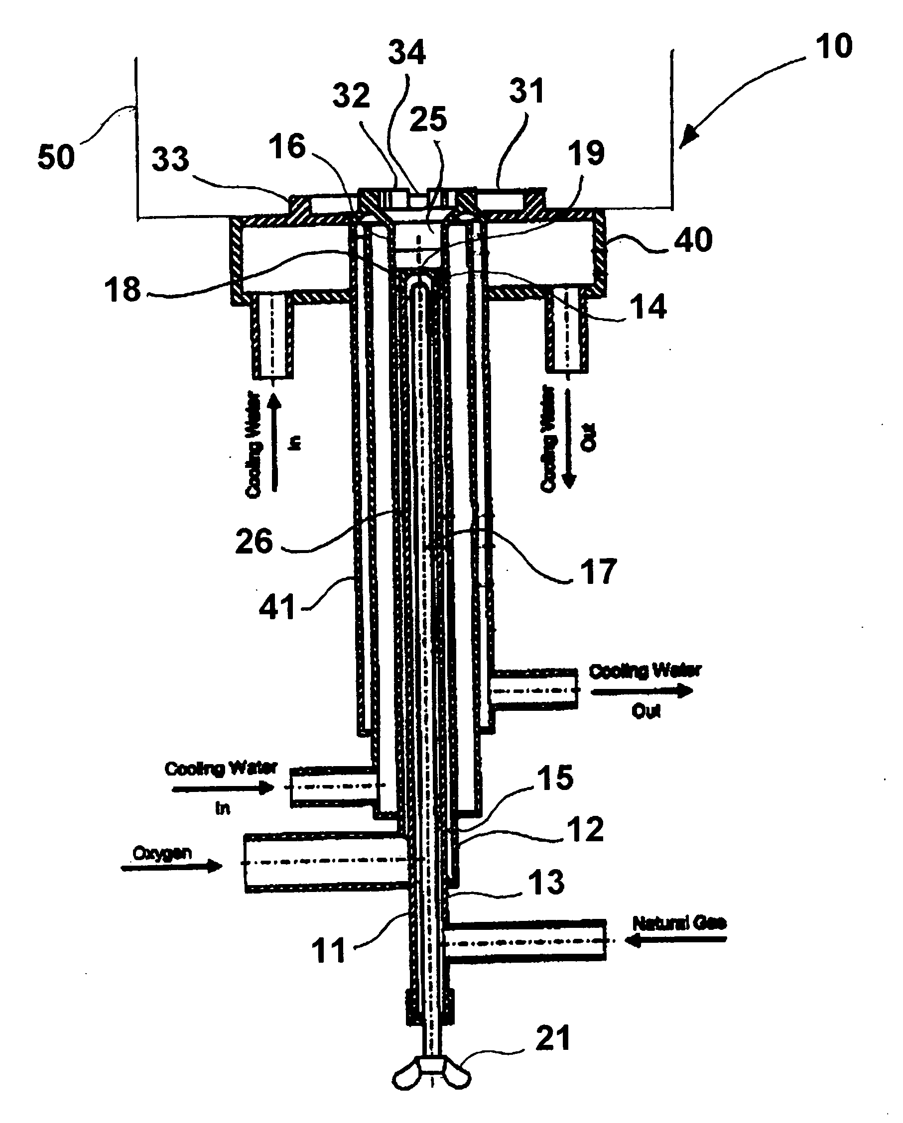
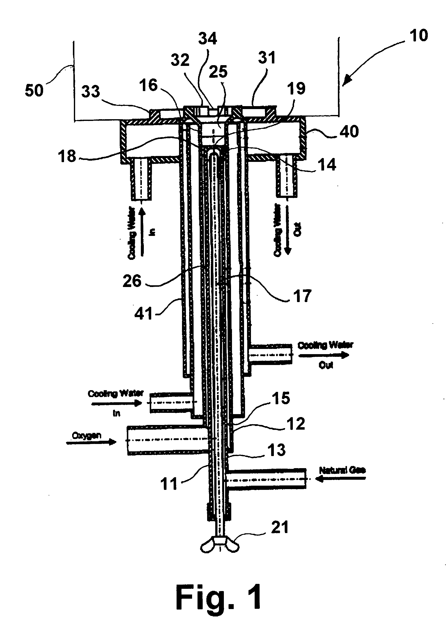
[0020] This invention relates to a method and apparatus in which a mixture of fuel and oxidant, also referred to herein as a fuel-oxidant mixture, is ignited to initiate combustion and the combustion products so generated are introduced directly into a volume of material being melted. The invention provides constant, reliable, and rapid ignition of the fuel-oxidant mixture while maintaining a stable flame beneath the surface of the melt such that the mixture burns quickly and releases the heat of combustion directly into the melt. The burner supplies energy to the material being melted in the form of thermal energy (heat release) and mechanical energy (injection of the fuel-oxidant mixture). Simultaneously therewith, the method and apparatus of this invention create a well-mixed, or homogeneous, melt from the action of the combustion products within the material being melted. This is achieved by injection of high-momentum jets of the combustion products into the melt, which improves...


PUM

PropertyMeasurementUnit
velocityaaaaaaaaaa
velocityaaaaaaaaaa
diameteraaaaaaaaaa

Abstract

A submerged combustion burner having co-axial fuel and oxidant tubes forming an annular space therebetween, wherein the outer tube extends beyond the end of the inner tube. A burner nozzle having an outside diameter corresponding to the inside diameter of the outer tube is connected to the outlet end of the inner tube and forms a centralized opening in fluid communication with the inner tube and at least one peripheral longitudinally oriented opening in fluid communication with the annular space. In accordance with one embodiment, a longitudinally adjustable rod is disposed within the inner tube for adjustment of fluid flow therethrough, and a cylindrical insert having at least one flame stabilizer for stabilizing a flame produced by the burner is attached to the outlet end of the outer tube. In accordance with another embodiment, fluid flow through the inner tube is achieved by a flow control valve operably connected to the inner tube.

Description

BACKGROUND OF THE INVENTION [0001] 1. Field of the Invention [0002] This invention relates to a method and apparatus for submerged combustion melting, that is, a method and apparatus in which the hot products of combustion are introduced directly into a material for melting, such as glass, through an opening in the melt containment vessel disposed below the level of the material present in the melt containment vessel. [0003] 2. Description of Related Art [0004] The concept of submerged combustion is not new. Most of the burners that have been developed for this purpose are applicable to aqueous systems. However, burners suitable for use in the melting of high melting temperature materials, such as glass, metals, etc. are also known. U.S. Pat. No. 3,260,587 to Dolf et al. teaches a method and apparatus for submerged combustion melting of glass or similar materials in which a burner having an air cooled casing is inserted into a furnace wall, either the furnace side wall or the furnac...

Claims


Application Information

Patent Timeline
Patent Type & Authority Applications(United States)
IPC IPC(8): C03B5/16C03B5/235F23D14/32F23D14/78F23D14/84F27B3/04F27B3/20F27B3/28F27D19/00F27D99/00
CPCC03B5/2356F23D14/22F23D14/78F23D14/84F23D2900/00018F27B3/045F27B3/205F27B3/28F27D19/00F27D99/0033F27D2099/0036F27D2099/0055F27D2099/0056Y02E20/344F23C3/004F23D14/32
Inventor RUE, DAVID M.ABBASI, HAMID A.KHINKIS, MARK J.OLABIN, VLADIMIR M.MAKSYMUK, OLEKSANDR
Owner GAS TECH INST
Why Eureka
Try Eureka