Frequency output circuit

a frequency output circuit and output circuit technology, applied in logic circuit coupling/interface arrangement, pulse technique, instruments, etc., can solve the problems of radio noise, inability to provide current limit when the voltage increases, and inability to completely eliminate unwanted electromagnetic waves, so as to achieve the effect of reducing radio nois

Active Publication Date: 2005-10-27
HITACHI ASTEMO LTD
View PDF15 Cites 6 Cited by
  • Summary
  • Abstract
  • Description
  • Claims
  • Application Information

AI Technical Summary

Benefits of technology

[0024] In accordance with the invention, unwanted electromagnetic waves can be eliminated in a frequency output circuit with an open-collector output terminal, so that radio noise can be reduced.

Problems solved by technology

However, in the frequency output circuit with an open-collector output terminal that is provided with a current mirror circuit, a current limit cannot be provided when the voltage increases.
Even when the voltage decreases, the voltage change is not smooth, making it impossible to completely eliminate unwanted electromagnetic waves.
It has been found, however, that if the AM frequency is thus lowered, the unwanted electromagnetic waves emitted from the frequency output circuit with an open-collector output terminal, which previously had not been an issue, could provide radio noise.

Method used


Image

  • Frequency output circuit
  • Frequency output circuit
  • Frequency output circuit

Examples


first embodiment

[0039] Hereafter, the frequency output circuit according to the present invention will be described with reference to FIGS. 1 to 4.

[0040] Initially referring to FIGS. 1 and 2, the configuration and operation of the frequency output circuit of the present embodiment will be described.

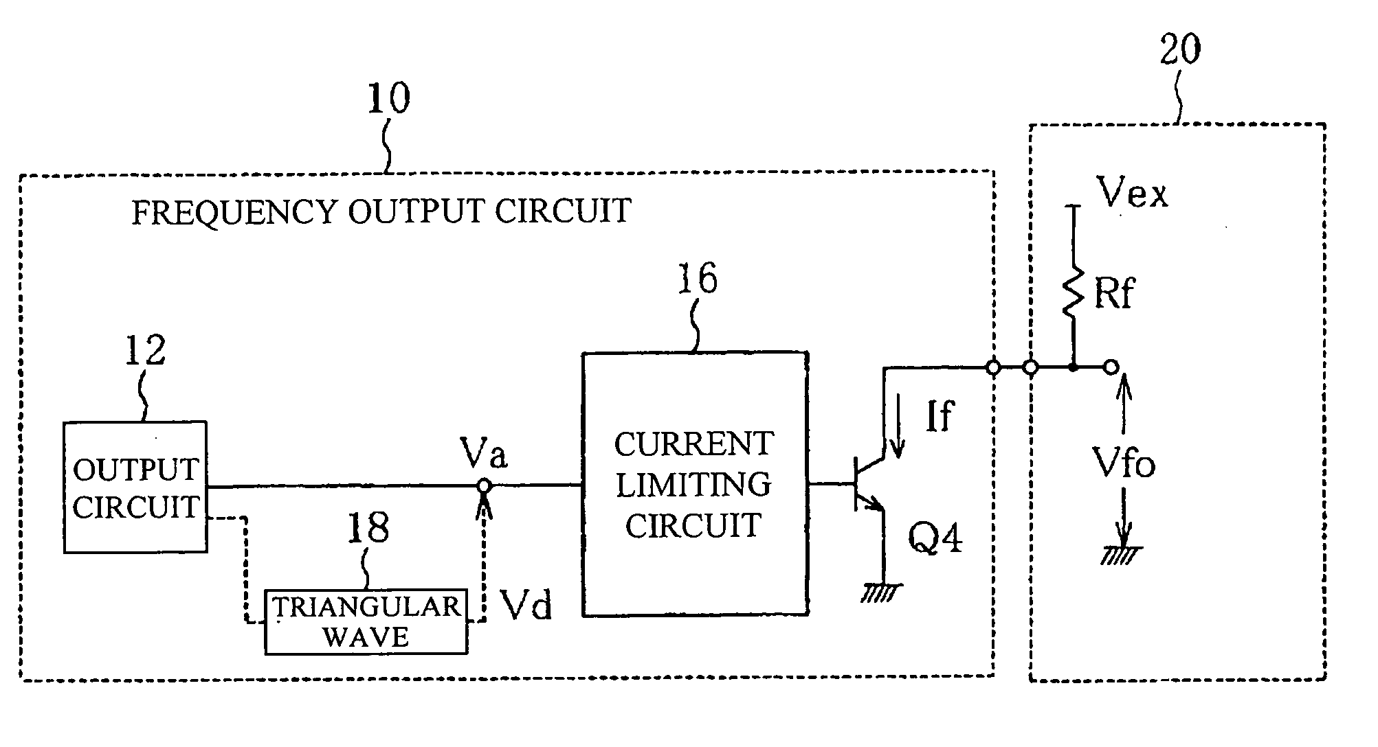
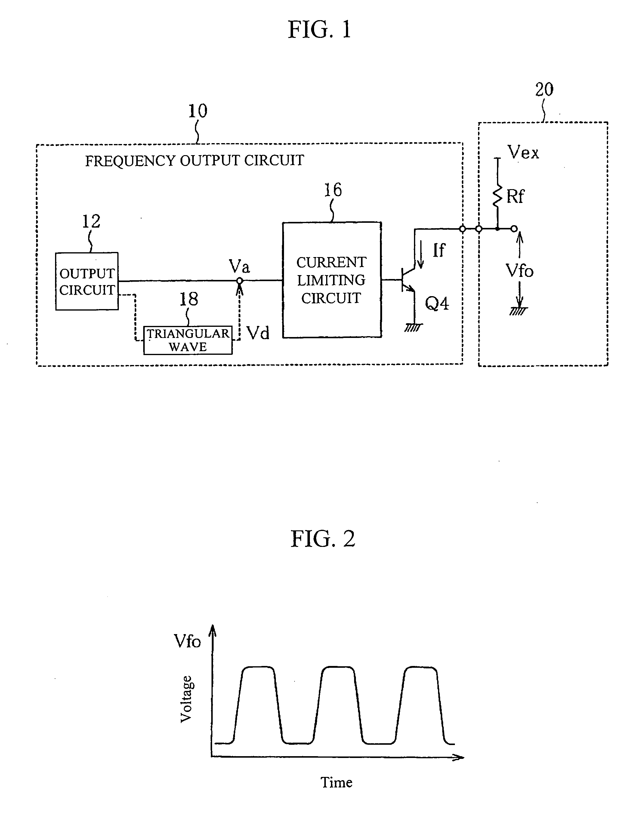
[0041]FIG. 1 shows a circuit diagram illustrating the configuration of the frequency output circuit according to the first embodiment of the present invention. FIG. 2 shows an output characteristics chart of the frequency output circuit of the first embodiment of the present invention.

[0042] A frequency output circuit 10 comprises an output circuit 12, a current limiting circuit 16, and an open-collector transistor Q4. A triangular wave generating circuit 18 will be described later. The output circuit 12 measures airflow rate, for example, as does a frequency output-type airflow meter, and produces output that varies depending on the airflow rate. Obviously, the output circuit 12 may be any device whos...

second embodiment

[0058] With reference to FIGS. 1 and 5, the configuration of the frequency output circuit in accordance with the invention is described.

[0059]FIG. 5 shows the operation of the frequency output circuit in the second embodiment of the invention.

[0060] The present embodiment characteristically comprises a triangular wave conversion circuit 18, as shown in FIG. 1. The path directly leading from the output circuit 12 to the current limiting circuit 16 is removed. The triangular wave conversion circuit 18 converts the output of the output circuit 12, if it is a rectangular wave, into a triangular wave, as shown in FIG. 5.

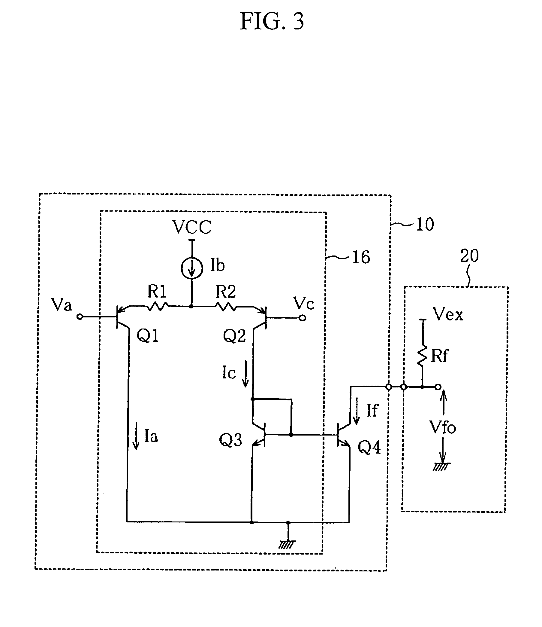
[0061] If Va is an ideal rectangular wave where the voltage switching time is zero, the switching of the output voltage Vfo would also be sharp, as will be seen from FIG. 4 and equation (5). This is due to the fact that the switching from Va>Vc would be fast and it would take only a short time before Va≈Vc. Although such an ideal rectangular wave does not generally occu...

third embodiment

[0064] With reference to FIGS. 6 and 7, the configuration of the frequency output circuit will be described.

[0065]FIG. 6 shows a circuit diagram illustrating the configuration of the frequency output circuit according to the third embodiment of the invention. FIG. 7 shows an operational waveform chart of the frequency output circuit of the third embodiment. Similar reference numerals designate similar elements in FIGS. 1 and 3.

[0066] A current limiting circuit 16A includes an amplifier AMP 1 connected to transistor Q 1, in addition to having the configuration shown in FIG. 3. An input signal Vd transmitted to the current limiting circuit 16A is a frequency signal of a triangular wave. The frequency signal Vd of the triangular wave has its amplitude changed by being amplified by the amplifier AMP1 before being fed to the base of transistor Q1. The frequency signal Vd of the triangular wave is also directly fed to the base of transistor Q2 as a reference signal Vc.

[0067] The relati...


PUM


Abstract

Unwanted electromagnetic waves are eliminated in a frequency output circuit comprising an open-collector output terminal whereby radio noise can be reduced. A frequency output circuit 10 comprises an open-collector transistor Q4 with an open-collector output terminal connected to a pull-up resistor Rf connected to an external power supply Vex. A current limiting circuit 16 limits a current through the output terminal such that a high potential and a low potential of the output waveform of a frequency signal outputted by an output circuit 12 are smoothly switched. The current limiting circuit 16 is formed by a differential pair circuit of transistors Q1 and Q2 each with a resistor provided in the emitter thereof, and a current mirror circuit comprising an open-collector transistor, for example.

Description

BACKGROUND OF THE INVENTION [0001] 1. Field of the Invention [0002] The present invention relates to a frequency output circuit for outputting a frequency signal, and, in particular, to a frequency output circuit comprising an open-collector output terminal. [0003] 2. Background Art [0004] In order to reduce the emission of unwanted electromagnetic radiation from a frequency output circuit, the circuit should ideally output a sine wave. JP Patent Publication (Kokai) No. 2001-211047 A discloses that, in the case of a rectangular wave oscillator that is not of the open-collector output configuration, a rectangular wave is shaped to be closer to a sine wave using an inductor and a capacitor such that the unwanted electromagnetic radiation can be eliminated. [0005] In frequency output circuits with an open-collector output terminal, the transistor on the output end is turned on or off and the signal voltage is received from an external power supply, such that the waveform that is output...

Claims


Application Information

Patent Timeline
Patent Type & Authority Applications(United States)
IPC IPC(8): H03K19/003G01F15/00G01F15/06H03F3/45H03K17/16H03K19/0175
CPCG01F15/00G01F15/068H03F2203/45686H03F2200/114H03F2203/45674H03F3/45085
Inventor ANDO, RYO
Owner HITACHI ASTEMO LTD
Why Eureka
Try Eureka