

Illumination optical system, exposure apparatus and device fabrication method
a technology of exposure apparatus and optical system, applied in the direction of polarising elements, printing, instruments, etc., can solve the problem of limited light source short wavelength of glass material with high transmittan
- Summary
- Abstract
- Description
- Claims
- Application Information
AI Technical Summary
Benefits of technology
Problems solved by technology
Method used
Image

Examples
first embodiment
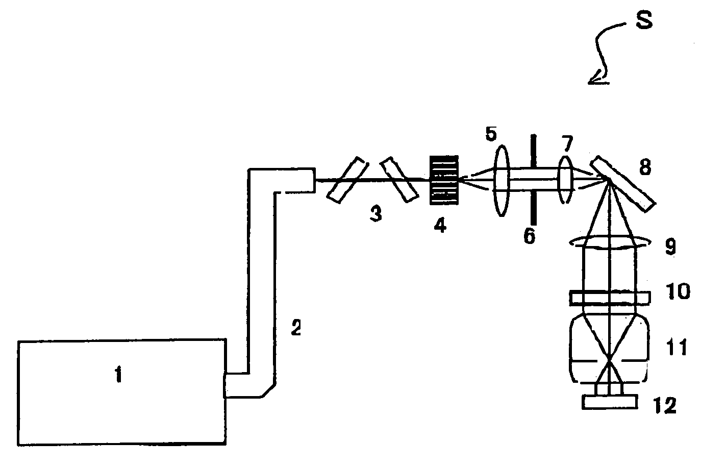
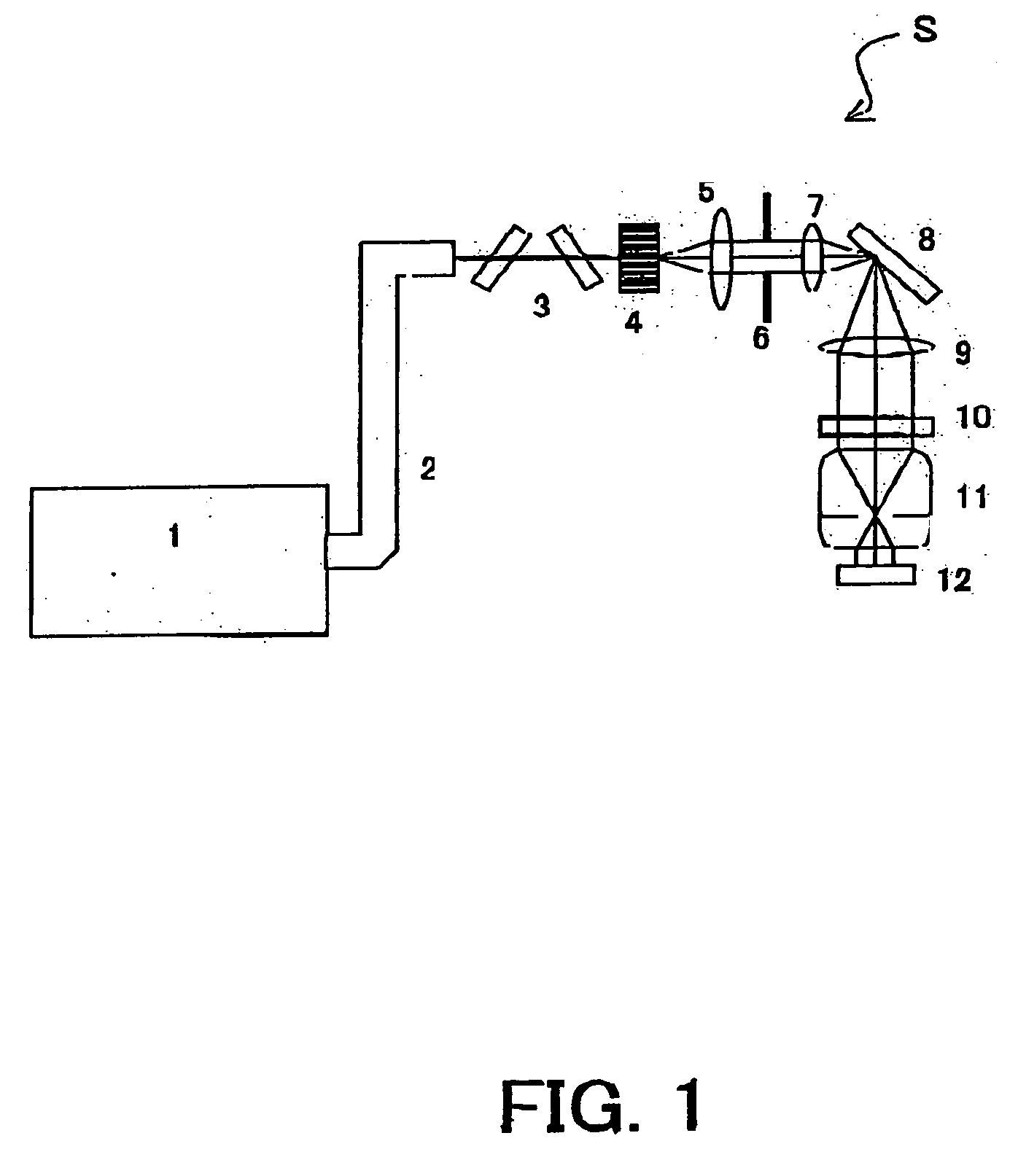
[0039] With reference to FIG. 1, a description will be given of an illumination optical system of the first embodiment according to the present invention. FIG. 1 is a schematic structure view of an exposure apparatus S that includes the illumination optical system of the instant embodiment. A light source 1 uses KrF excimer laser, ArF excimer laser, or F2 laser etc. A beam shaping optical system 2 channels a light from the light source 1, and forms a desired light intensity distribution on a fly-eye lens 4. A polarizing element 3 adjusts a polarization ratio to be a predetermined polarization ratio at a reticle 10 surface (target surface). The fly-eye lens 4 wavefront-divides the light from the light source 1, and forms a plural secondary light source. A condenser lens 5 overlaps light from the secondary light source formed by the fly-eye lens 4 to the masking blade 6. Thereby, a uniformly light intensity distribution is obtained. A lens 7 and a lens 9 as an optical element are a re...
second embodiment
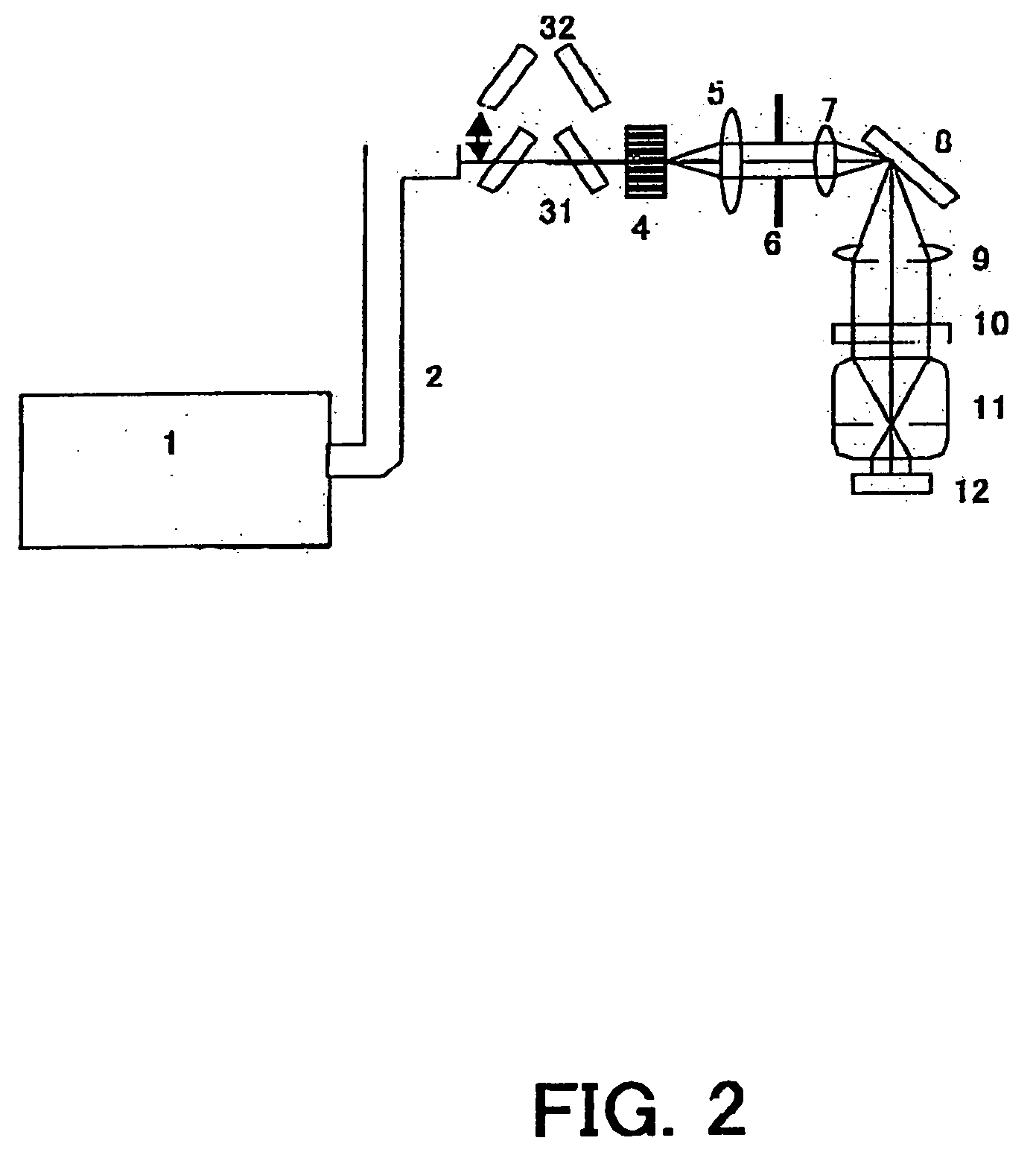
[0042] With reference to FIGS. 1 and 2, a description will be given of an illumination optical system of the second embodiment according to the present invention. A schematic structure of an exposure apparatus that includes the illumination optical system of the second embodiment is almost the same as the first embodiment. The light source 1 uses KrF excimer laser, ArF excimer laser, or F2 laser etc. The beam shaping optical system 2 leads the light from the light source 1, and forms the desired light intensity distribution on the fly-eye lens 4. The polarizing element 3 adjusts the polarization ratio to be the predetermined polarization ratio at the reticle 10 surface. The fly-eye lens 4 wavefront-divides the light from the light source 1, and forms the plural secondary light source. The condenser lens 5 overlaps light from the secondary light source formed by the fly-eye lens 4 to the masking blade 6. Thereby, the uniformly light intensity distribution is obtained. The lens 7 and ...
third embodiment
[0046] With reference to FIG. 3, a description will be given of an illumination optical system of the third embodiment according to the present invention. FIG. 3 is a schematic structure view of an exposure apparatus S that includes the illumination optical system of the instant embodiment. The light source 1 uses KrF excimer laser, ArF excimer laser, or F2 laser etc. A random polarized plate 15 polarizes the light from the light source 1 in two orthogonal directions, and forms two light beams from a random polarized light of the light intensity ratio of 1:1. The random polarized plate 15 uses a parallel flat plate that stacks a sphenoid member formed from a birefringent material and a sphenoid member formed from a non-birefringent material. The beam shaping optical system 2 channels the light from the light source 1, and forms the desired light intensity distribution on the fly-eye lens 4. The fly-eye lens 4 wavefront-divides the light from the light source 1, and forms the plural ...
PUM
| Property | Measurement | Unit |
|---|---|---|
| width | aaaaa | aaaaa |
| width | aaaaa | aaaaa |
| wavelength | aaaaa | aaaaa |
Abstract
Description
Claims
Application Information