
Electro-magnetophoresis display

a technology of electromagnetic field and display, applied in the field of electromagnetic field, can solve the problems of significant increase in display driving voltage or a decrease in switching rate, affecting the bias across, and affecting the accuracy of the display, so as to prevent undesired movement of charged particles, avoid the effect of cross-talk and/or cross-bias, and high color quality

Inactive Publication Date: 2005-11-03
E INK CALIFORNIA
View PDF26 Cites 9 Cited by
  • Summary
  • Abstract
  • Description
  • Claims
  • Application Information

AI Technical Summary

Benefits of technology

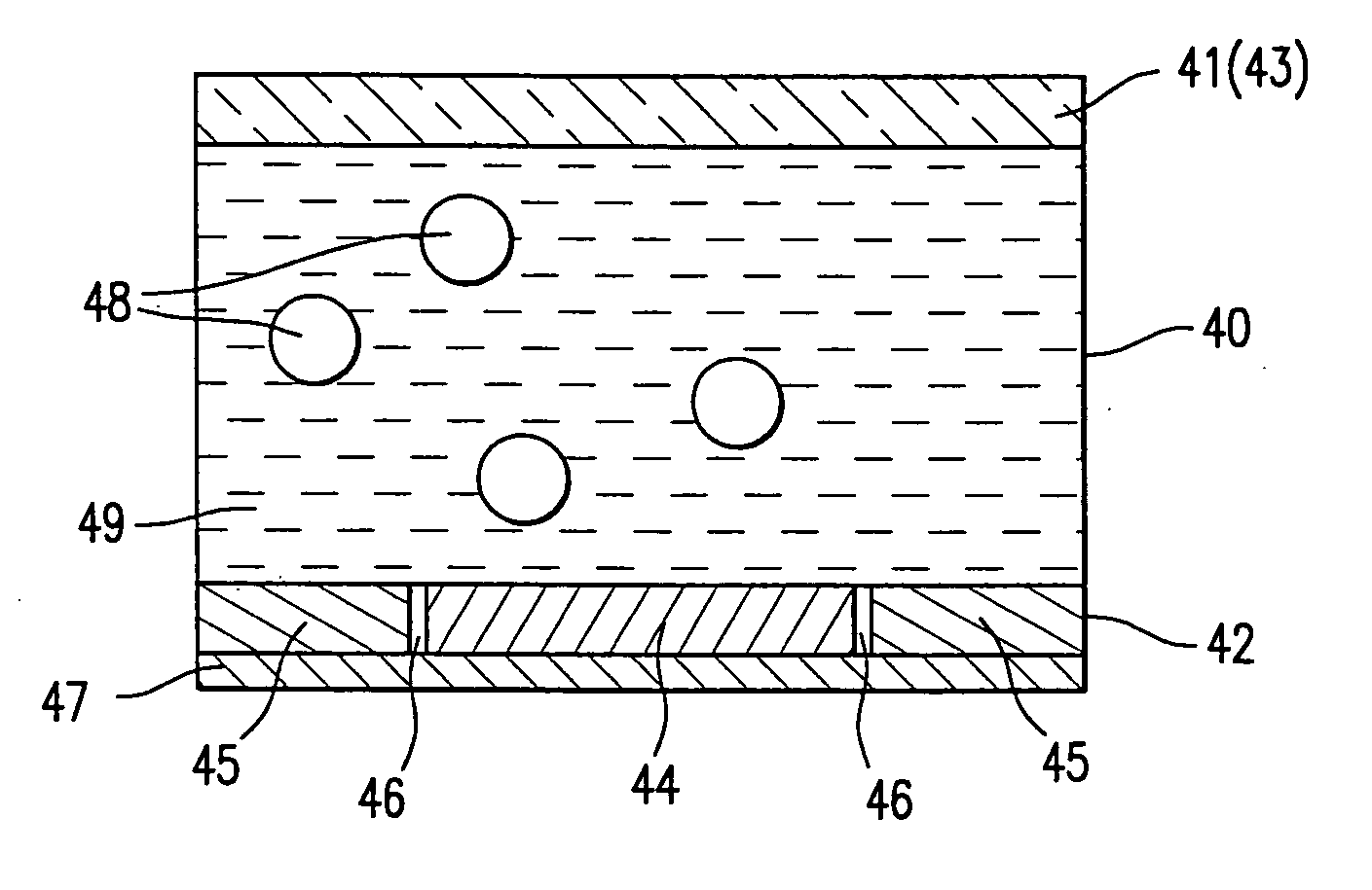
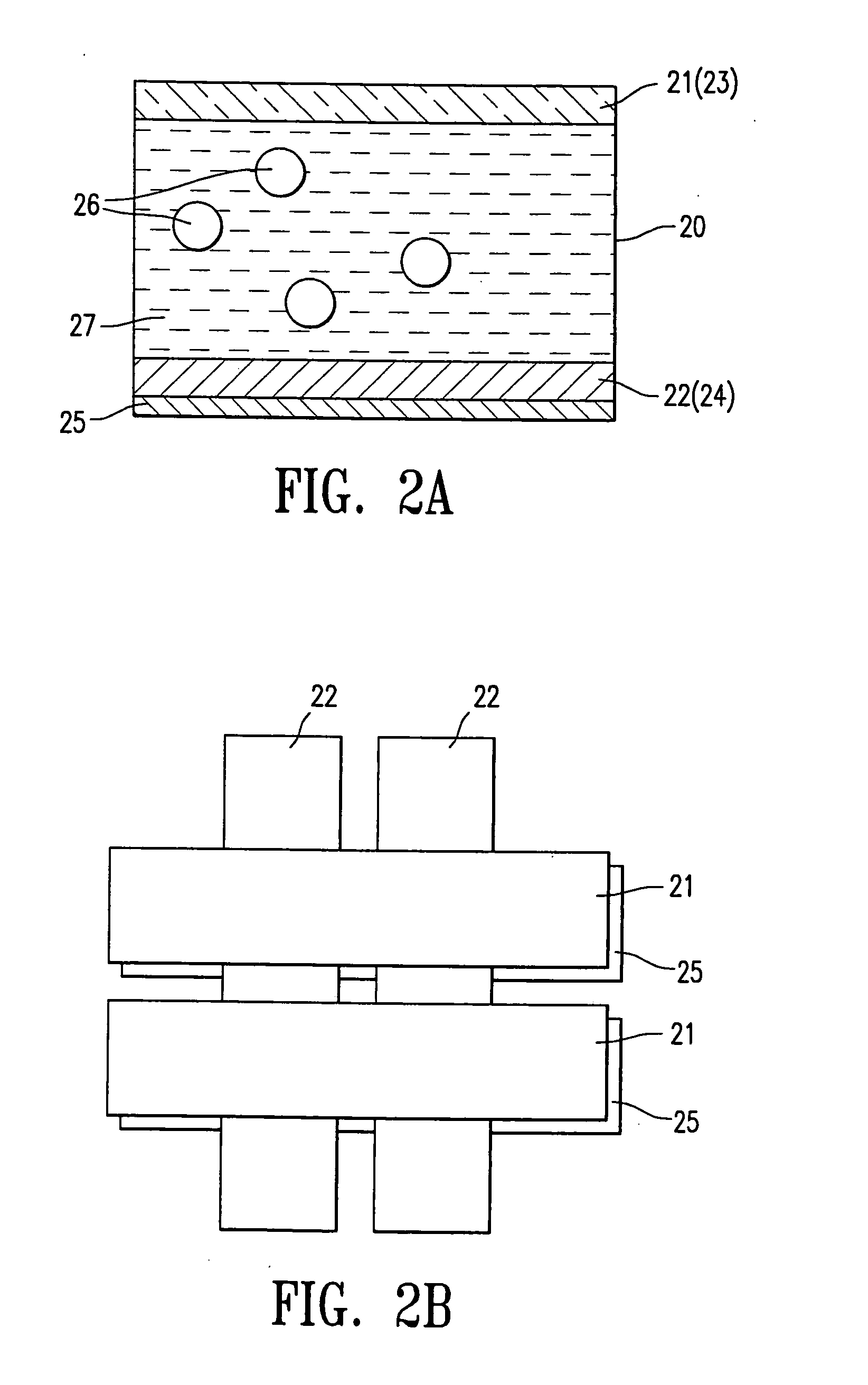
The present invention is about an electro-magnetophoresis display with a traditional up / down switching mode or a dual mode. The display comprises electrodes and cells filled with charged magnetic particles dispersed in a contrast-colored dielectric solvent. The charged particles are attracted to the viewing side and the color of the particles is seen. The design prevents undesired movement of the charged particles and allows the particles to move in both the up / down and planar direction, resulting in a multicolor display with high color quality at low cost. The technical effects of the invention include preventing cross-talk and cross-bias effects, providing a stable display, and allowing for a variety of display modes.

Problems solved by technology

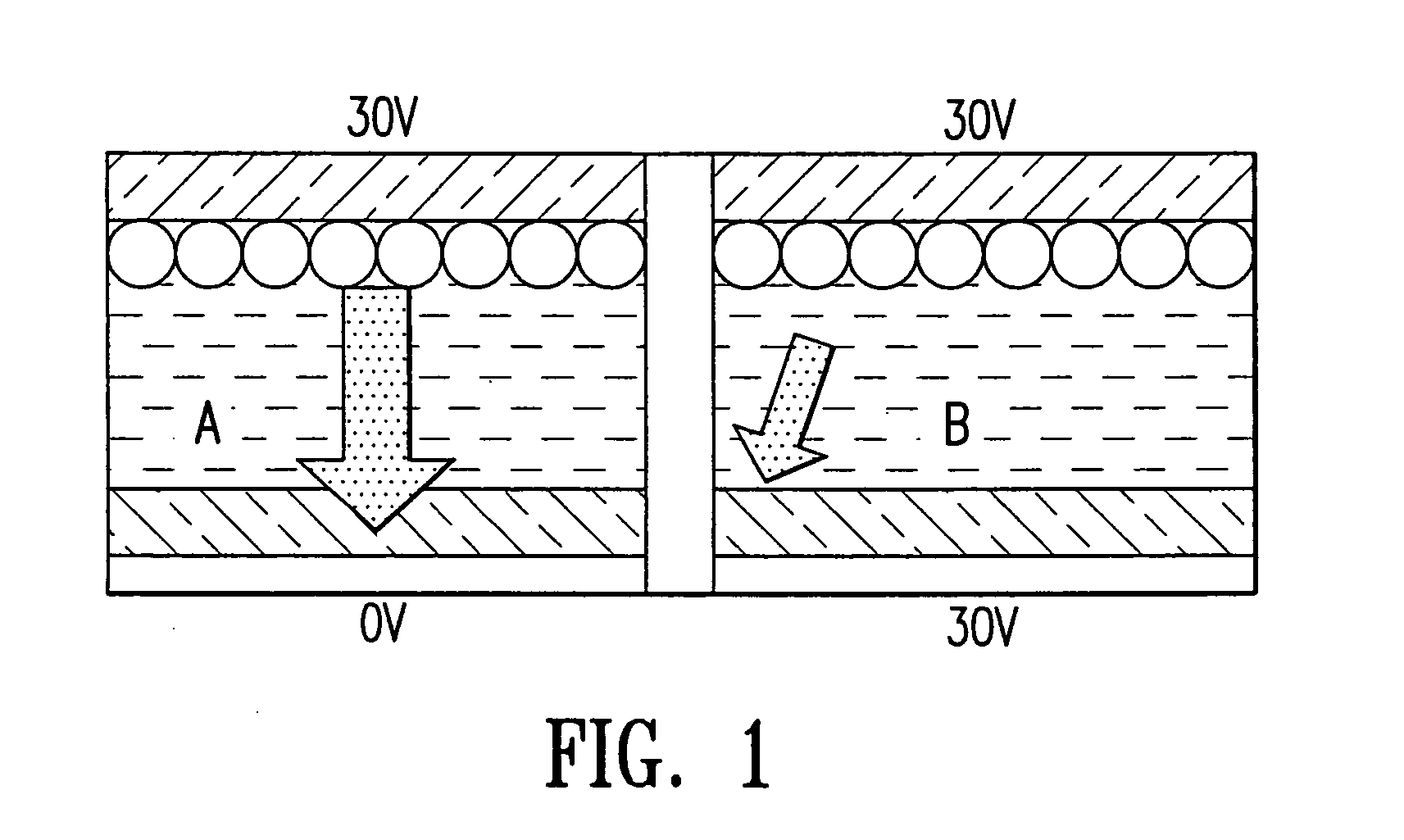
However, there are two well-known problems which are associated with EPDs driven by a passive matrix system: cross-talk and cross-bias.
Unfortunately, most approaches to increase the threshold voltage tend to result in a significant increase in display driving voltage or a decrease in switching rate.
The voltage applied to a column electrode not only provides the driving bias for the cell on the scanning row, but it also affects the bias across the non-scanning cells on the same column.
This undesired bias may force the particles of a non-scanning cell to migrate to the opposite electrode.
This results in changes in image density and a significant deterioration of the display contrast.
Although these references teach how the threshold voltage may be raised by the use of gating electrodes, the cost for fabricating the two electrode layers is extremely high due to the complexity of the structure and the low yield rate.
In addition, in this type of EPDs, the electrodes are exposed to the solvent, which could result in an undesired electroplating effect and deterioration in the display operation longevity.
The in-plane electrodes are significantly more difficult to manufacture than the normal up-down electrodes, particularly for high resolution displays.
Moreover, the color saturation of a color display will be poor due to the lack of either true white or true black state.

Method used


Image

  • Electro-magnetophoresis display
  • Electro-magnetophoresis display
  • Electro-magnetophoresis display

Examples


Embodiment Construction

[0025] A detailed description of representative embodiments of the invention is provided below. While the invention is described in conjunction with representative embodiments, it should be understood that the invention is not limited to these embodiments. In order to meet the specific requirements of a particular EMPD, the design and dimensions of the features may vary and all such variations are within the scope of the present invention. To illustrate this invention, numerous specific details are set forth in the following description. The present invention may be practiced according to the claims without some or all of these specific details. For the purpose of clarity, technical material that is known in the technical fields related to the invention has not been described in detail so that the present invention is not unnecessarily obscured.

I. Definitions

[0026] Unless defined otherwise in this specification, all technical terms are used herein according to their conventional ...


PUM

PropertyMeasurementUnit
driving voltageaaaaaaaaaa
voltageaaaaaaaaaa
voltageaaaaaaaaaa

Abstract

The present invention is directed to an electro-magnetophoresis display having either the traditional up / down or dual switching mode. The display cells are filled with an electro-magnetophoretic dispersion comprising particles suspended in a solvent and the particles are both charged and magnetized. The display of the invention prevents undesired movement of the particles in the cells. The magnetic force generated by the magnetic layer(s) eliminates the need to provide cells with a threshold voltage high enough to avoid the cross talk and / or cross bias effects. In addition, the dual switching mode allows the particles to move in the up / down direction as well as the planar direction, thus providing a multicolor display of high color quality at very low cost.

Description

CROSS-REFERENCE TO RELATED APPLICATIONS [0001] This application is a continuation-in-part application of U.S. Ser. No. 10 / 421,217 filed Apr. 22, 2003 and also a continuation-in-part application of U.S. Ser. No. 09 / 518,488 filed Mar. 3, 2000, the contents of both of which are incorporated herein by reference in their entirety.BACKGROUND OF THE INVENTION [0002] The electrophoretic display (EPD or EPID) is a non-emissive device based on the electrophoresis phenomenon of charged pigment particles suspended in a solvent. It was first proposed in 1969. The display typically comprises two plates with electrodes placed opposing each other, separated by spacers. One of the electrodes is usually transparent. A suspension composed of a colored solvent and charged pigment particles, is enclosed between the two plates. When a voltage difference is imposed between the two electrodes, the pigment particles migrate to one side and then either the color of the pigment or the color of the solvent can...

Claims


Application Information

Patent Timeline
Patent Type & Authority Applications(United States)
IPC IPC(8): G02B26/00G02F1/09H01L27/10H01L29/74
CPCG02F2001/094G02F1/09G02F1/094
Inventor CHUNG, JERRYLIANG, RONG-CHANG
Owner E INK CALIFORNIA
Learn More