Electronic clock, electronic apparatus and starting method

a technology of electronic equipment and oscillation starting characteristics, applied in the field of electronic time, can solve the problems of crystal oscillation circuit not being installed in the electronic timepiece of a woman, crystal oscillation circuit cannot start, above problem becomes significant, etc., and achieves significant reduction of current required for oscillation behavior, improvement of oscillation starting characteristics, and reduction of power consumption

Active Publication Date: 2005-11-03
CITIZEN WATCH CO LTD
View PDF8 Cites 9 Cited by
  • Summary
  • Abstract
  • Description
  • Claims
  • Application Information

AI Technical Summary

Benefits of technology

[0028] According to still another aspect of the present invention, in the electronic timepiece, the timing unit is provided with a logic circuit constituted of a plurality of field effect transistors, and the oscillation inverter is constituted of a field effect transistor having a threshold voltage lower than that of the field effect transistor included in the timing unit.
[0029] According to still another aspect of the present invention, in the electronic timepiece, the timing unit is provided with a logic circuit constituted of a plurality of field effect transistors, and a waveform shaping unit that is constituted of a field effect transistor having a threshold voltage lower than that of the field effect transistor included in the timing unit and that shapes a waveform of an oscillation signal outputted from the oscillation signal output unit to output the same to the timing unit.
[0030] According to still another aspect of the present invention, in the electronic timepiece, the timing unit is provided with a logic circuit constituted of a plurality of field effect transistors, and the boosting control unit is constituted of a field effect transistor having a threshold voltage lower than that of the field effect transistor included in the timing unit.
[0031] According to still another aspect of the present invention, the electronic timepiece further includes a bias circuit that is constituted of a field effect transistor having the same threshold as that of the oscillating circuit and that applies a predetermined bias voltage to the oscillation inverter.
[0032] According to still another aspect of the present invention, the electronic timepiece further includes a waveform shaping unit that shapes a waveform of an oscillation signal outputted from the oscillation signal output unit to output the same to the timing unit, and a bias circuit that is constituted of a field effect transistor having the same threshold as that of the waveform shaping unit and that applies a predetermined bias voltage to the waveform shaping unit. According to the present invention, reduction in power consumption can be achieved. A current required for an oscillation behavior can be reduced significantly, and improvement in oscillation starting characteristics can be achieved.

Problems solved by technology

As a result, there is a problem that the crystal oscillation circuit can not start.
Particularly, since an electronic timepiece for a woman is smaller than an electronic timepiece for a man, it must use a solar battery with a small effective light-receiving area, so that the above problem becomes significant.
Therefore, there is another problem that the crystal oscillation circuit can not be installed in the electronic timepiece for a woman.
However, since a light-receiving area in the solar battery can not be enlarged due to a structure of a timepiece, it is necessary to receive not only direct light but also light reflected from the timepiece dial.
Accordingly, since only a white-base color, which reflects light, can be adopted for the timepiece dial, there is such a problem that the timepiece dial is restricted regarding its design.

Method used


Image

  • Electronic clock, electronic apparatus and starting method
  • Electronic clock, electronic apparatus and starting method
  • Electronic clock, electronic apparatus and starting method

Examples


Embodiment Construction

[0053] An electronic timepiece and an actuating method of the electronic timepiece according to an embodiment of the present invention will be explained below in detail with reference to the drawings.

(Whole Configuration of Electronic Watch)

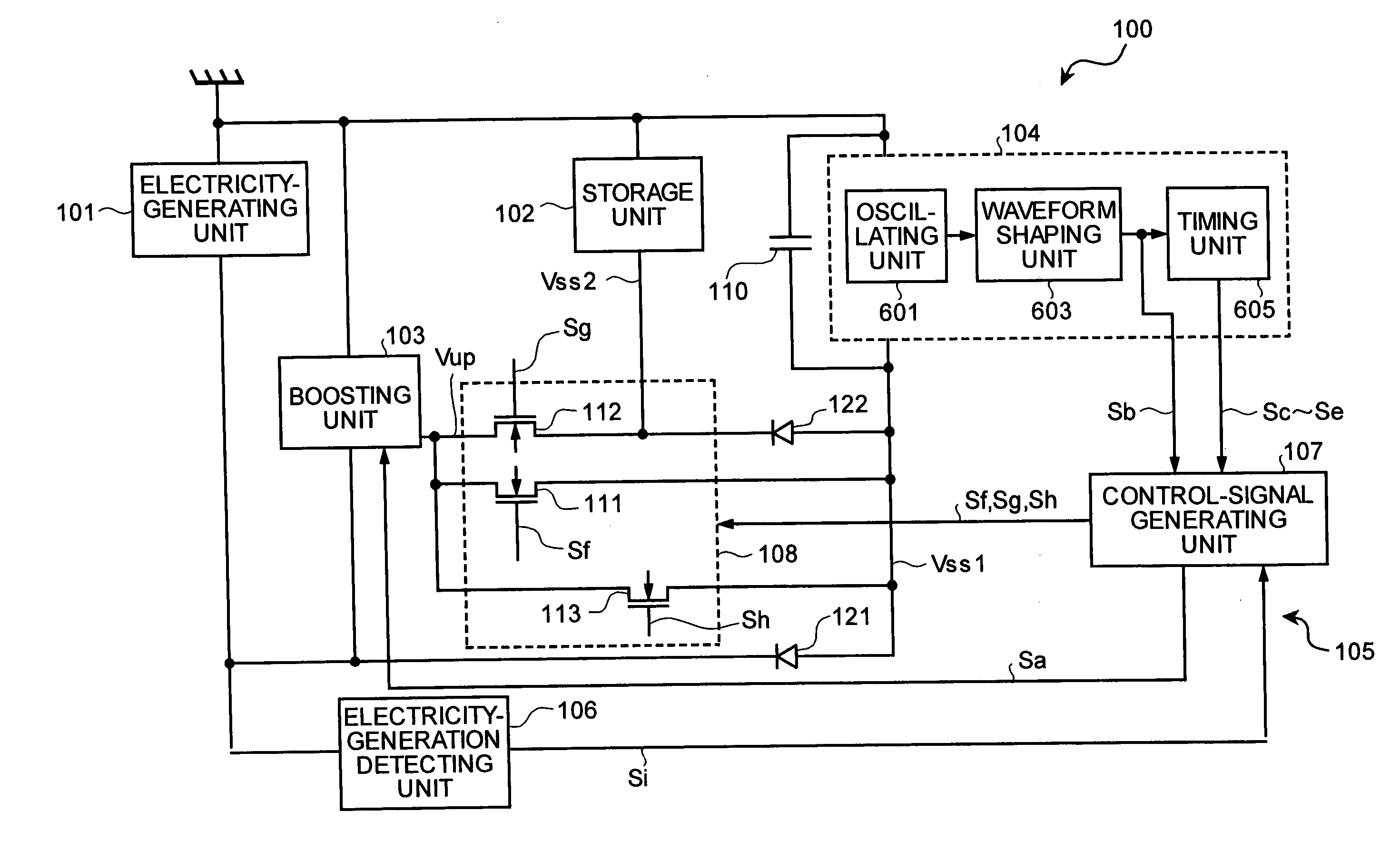
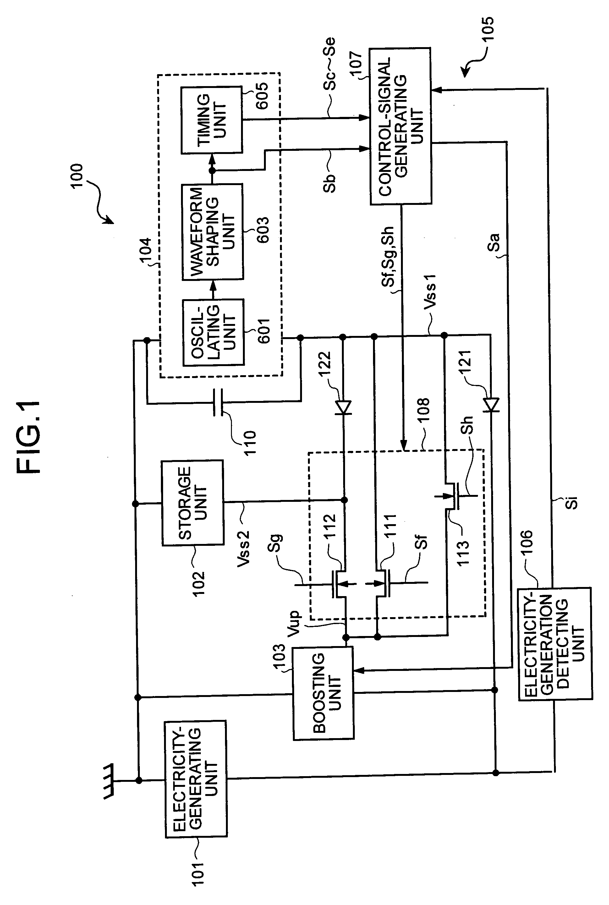
[0054]FIG. 1 is a schematic of a whole configuration of an electronic timepiece according to an embodiment of the present invention. An electronic timepiece 100 includes an electricity-generating unit 101, a storage unit 102, a boosting unit 103, a timepiece block 104, a boosting control unit 105, and an electricity-generation detecting unit 106.

[0055] The electricity-generating unit 101 converts external energy to electric energy and generates a power source voltage lower than a predetermined operating voltage that activates the electronic timepiece 100. The electricity-generating unit 101 is a solar battery module constituted of, for example, a one-stage solar cell. A positive terminal of the electricity-generating unit 101 is grounded and ...


PUM


Abstract

Using an oscillating unit (601) that can start oscillation with a low voltage, an oscillation signal (S1) of the oscillating unit (601) is amplified via a waveform shaping unit (603), and is fed to a boosting control unit (105). A boosting unit (103) is caused to perform a boosting behavior by a boosting clock (Sa) with the same frequency as an oscillation frequency of the oscillation signal (S1) just after the oscillating unit (601) starts. Thereby, a whole electronic timepiece (100) can be self-actuated, even if a generation voltage is low. Further, the oscillating unit (601) is constituted such that a operating current always becomes constant. Thereby, the electronic timepiece can be provided with an electricity-generating unit (101) such as a solar cell with a one-stage constitution having a low open voltage.

Description

TECHNICAL FIELD [0001] The present invention relates to an electronic timepiece and an electronic device that time or operate by applying a predetermined operating voltage thereto, and an actuating method therefor. In particular, the present invention relates to an electronic timepiece and an electronic device that converts external energy to electric energy, and an actuating method therefor. BACKGROUND ART [0002] Electronic timepieces with an electricity-generating unit that converts external energy such as optical or mechanical energy to electric energy to utilize the electronic energy for driving an electronic device have been proposed. [0003] Examples of an electronic timepiece with such electricity-generating unit are a mechanically electricity-generating type timepiece that converts mechanical energy of a rotary weight to electric energy to utilize the same, a temperature-difference electricity-generating type timepiece that generates electric power by serializing a plurality ...

Claims


Application Information

Patent Timeline
Patent Type & Authority Applications(United States)
IPC IPC(8): G04C10/02G04F5/06G04G19/04H02M1/00H02M1/36H02M1/42H02M3/07H03B5/06H03B5/32
CPCG04C10/02G04F5/06G04G19/04H02M1/36Y02B70/126H02M3/07H03B5/06H03B5/32H02M1/4225Y02B70/10
Inventor NAGATA, YOICHI
Owner CITIZEN WATCH CO LTD
Why Eureka
Try Eureka