Rolling elements

a technology of rolling elements and gears, applied in the field of rolling elements, can solve the problems of damage to carburized quenched gears, affecting the performance of the reducer used for running and turning such machines, and impulsive load on the gears of the reducer used for running and turning such machines, and achieves excellent charpy impact characteristics, and improved impact load resistance of the gear

Inactive Publication Date: 2005-11-10
KOMATSU LTD
View PDF21 Cites 19 Cited by
  • Summary
  • Abstract
  • Description
  • Claims
  • Application Information

AI Technical Summary

Benefits of technology

[0016] It has also been understood from the comparison between the 300° C.-temper hardness of the carburization-hardened layer of the SCM420 steel which has undergone carburizing / quenching and the 300° C.-temper hardness of the eutectoid carbon steel which has undergone quenching that since virtually no improvement in temper softening resistance can be attained by additions of Cr and Mo, a new alloy design intended for increasing temper softening resistance during low-temperature tempering at about 300° C. is necessary in order to achieve pitting resistance equal to or more than that of the carburized, quenched gears by bright hardening or induction hardening. Also, dispersion of fine cementite particles or the like in the martensitic phase has proved effective as seen from the cases of eutectoid carbon steel (0.82 wt % C) and SUJ2 which were improved in rolling contact fatigue strength.
[0069] Mo is a useful element as it improves the hardenability of steel and restrains temper brittleness, and therefore it is desirable for the invention to add Mo in an amount of 0.35 wt % or less which is at the same level as that of ordinary case-hardened steels.

Problems solved by technology

Construction machines and earth-moving machines often stride obstacles such as rocks and structures during travelling and drill the obstacles while making a turn, and therefore, the gears of the reducer used for running and turning such machines receive impulsive load.
This is a serious problem of damage to carburized quenched gears.
Bright-hardened or induction-hardened gears have higher toughness than carburized quenched gears, but are more likely to cause pitting or scuffing when they are used under high interface pressure such as noted above.

Method used


Image

  • Rolling elements
  • Rolling elements
  • Rolling elements

Examples


example 1

The Pitting Resistance of Quenched, Tempered Carbon Steel and Carburized, Quenched, Case-Hardened Steel

(Preliminary Test)

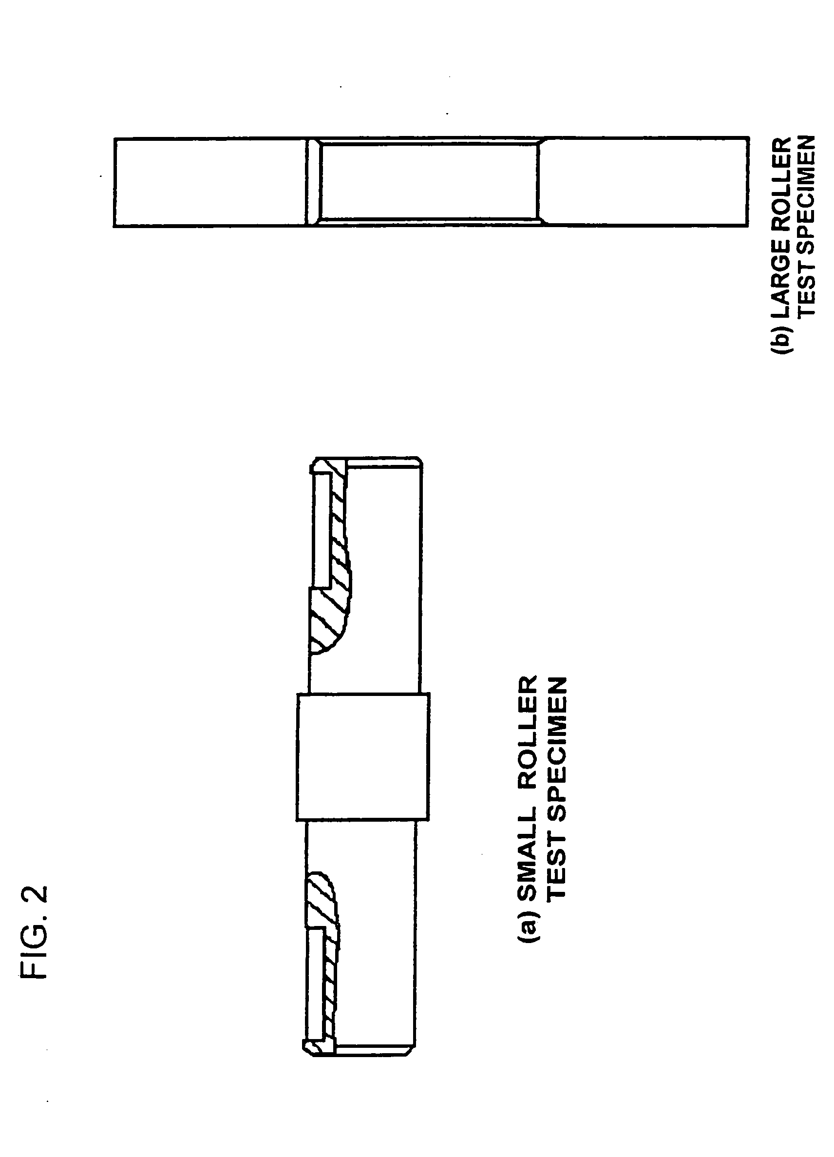
[0081] In this example, a roller pitting test was conducted with the test specimen shown in FIG. 2 and the pitting resistance of various quenched, tempered carbon steels and carburized, quenched, case-hardened steels was checked to investigate the rolling contact fatigue strength of the tooth flanks of gears. Table 1 shows the chemical compositions of the various carbon steels and case-hardened steels used in this example. These steel materials were respectively shaped into the small roller test specimen shown in FIG. 2(a) and the test specimens No. 1, 2 and 4 were subjected to water quenching after heating at 820° C. for 30 minutes, and then tempered at 160° C. for 3 hours, followed by testing. The specimen No. 3 was quench-hardened, at its rolling contact surface, using a 40 kHz high-frequency power source after thermal refining and then subjected to temperin...

example 2

Checking of Temper Softening Resistance

[0086] Table 2 shows the alloy compositions employed in this example. Thermal treatment was carried out in such a way that after heated at 810 to 870° C. for 30 minutes, each test specimen was subjected to water cooling and then tempering at 300° C. or 350° C. for 3 hours. Thereafter, the Rockwell hardness HRC of each test specimen was checked and the effect of the addition of each alloy element on the hardness was analyzed.

TABLE 2TPNo.CSiAlMnNiCrMoVBNo.60.451.450.461.490.520.140.0018No.70.491.450.461.011.030.150.0019No.80.470.310.462.011.030.150.0019No.90.490.290.451.51.490.230.0019No.100.361.770.60.620.110.0026No.110.450.950.680.011.290.50.0029No.120.390.931.020.080.970.950.5No.130.430.260.441.010.480.001No.140.470.250.41.011.050.0018No.150.461.50.410.510.002No.160.450.240.41.020.480.310.0011No.170.451.460.390.960.980.001No.180.410.250.3510.490.0017No.190.522.30.570.11No.200.980.270.481.47No.210.550.230.71No.220.770.210.74No.230.450.211.26...

example 3

An Improvement in Pitting Resistance by Use of Steel Materials Having Excellent Temper Softening Resistance 1

[0091] Table 3 shows the alloy components of the steel materials used in this example. The test specimens No. P1 to No. P10 were subjected to tempering at 160° C. for 3 hours subsequently to quenching at 850 to 920° C., whereas the test specimens No. 11 and No. 12 were subjected to induction hardening under the same high frequency heating condition as in Example 1. A roller pitting test was conducted on these test specimens.

TABLE 3300° C.CSiAlMnNiCrMoVBcalculated HRCNo.P10.340.211.471.170.170.1153.96No.P20.391.490.490.510.340.0553.91No.P30.411.510.720.320.1551.09No.P40.411.50.710.320.160.351.99No.P50.450.181.260.530.50.2155.94No.P60.551.510.710.150.1654.48No.P70.611.210.750.1454.34No.P80.620.211.240.530.1259.31No.P90.451.021.260.490.1258.78No.P100.610.251.470.930.981.040.3562.27No.P110.831.010.310.550.960.3862.11No.P121.210.20.520.521.010.510.466.62

[0092] The test for chec...


PUM

PropertyMeasurementUnit
contact fatigue strengthaaaaaaaaaa
pressureaaaaaaaaaa
temperatureaaaaaaaaaa

Abstract

The pitting resistance of a gear is increased by hardening its tooth flanks through application of carburizing / quenching, bright hardening and induction hardening to a steel material capable of providing significantly improved softening resistance in tempering at a low temperature of 300 to 350° C. To this end, the steel material prepared so as to satisfy the relationship described by: 5≦4.3×Si (wt %)+7.3×Al (wt %)+3.1×V (wt %)+1.5×Mo (wt %)+1.2×Cr (wt %)×(0.45÷C (wt %)) is carburized such that the carbon concentration of its carburized surface layer is adjusted to 0.6 to 0.9 wt %; and the steel material is subjected to quenching and tempering at 300° C. or less subsequently to the carburization process, or alternatively the steel material is once cooled after the carburization process and then subjected to treatments of re-heating hardening and tempering at 300° C. or less so that a hardness of HRC 58 or more is ensured by the tempering process at 300° C.

Description

CROSS REFERENCE TO RELATED APPLICATION [0001] This application is a Divisional application of U.S. application Ser. No. 10 / 641,362, filed on Aug. 13, 2003.TECHNICAL FIELD [0002] The present invention relates to rolling elements produced by carburizing and quenching, bright hardening or induction hardening. More particularly, the invention relates to gears and rolling elements such as bearings, races and rollers, the gears being made from steel which provides significantly improved resistance to softening caused in low-temperature tempering at 300 to 350° C. and having high pitting resistance in the tooth flanks hardened by carburizing / quenching, bright hardening or induction hardening. BACKGROUND ART [0003] Up to now, gears produced by applying carburizing / quenching, carburizing / carbonitriding / quenching to SCr-based, SCM-based or SNCM-based low carbon steel have been commonly employed in the reducers of construction machines and earth-moving machines, since high contact fatigue stre...

Claims


Application Information

Patent Timeline
Patent Type & Authority Applications(United States)
IPC IPC(8): C21D9/32C21D6/00C22C38/00C22C38/54C22C38/58C23C8/22C23C8/80
CPCC23C8/80C23C8/22
Inventor TAKAYAMA, TAKEMORIHAMASAKA, NAOJIMORIOKA, NORIKO
Owner KOMATSU LTD
Why Eureka
Try Eureka