

Fluid element
a technology of fluid elements and elements, applied in the field of fluid elements, can solve the problems of difficult miniaturization, difficult disposal of harmful analysis waste liquid, and difficult treatment system
- Summary
- Abstract
- Description
- Claims
- Application Information
AI Technical Summary
Benefits of technology
Problems solved by technology
Method used
Image

Examples
first embodiment
(First Embodiment)
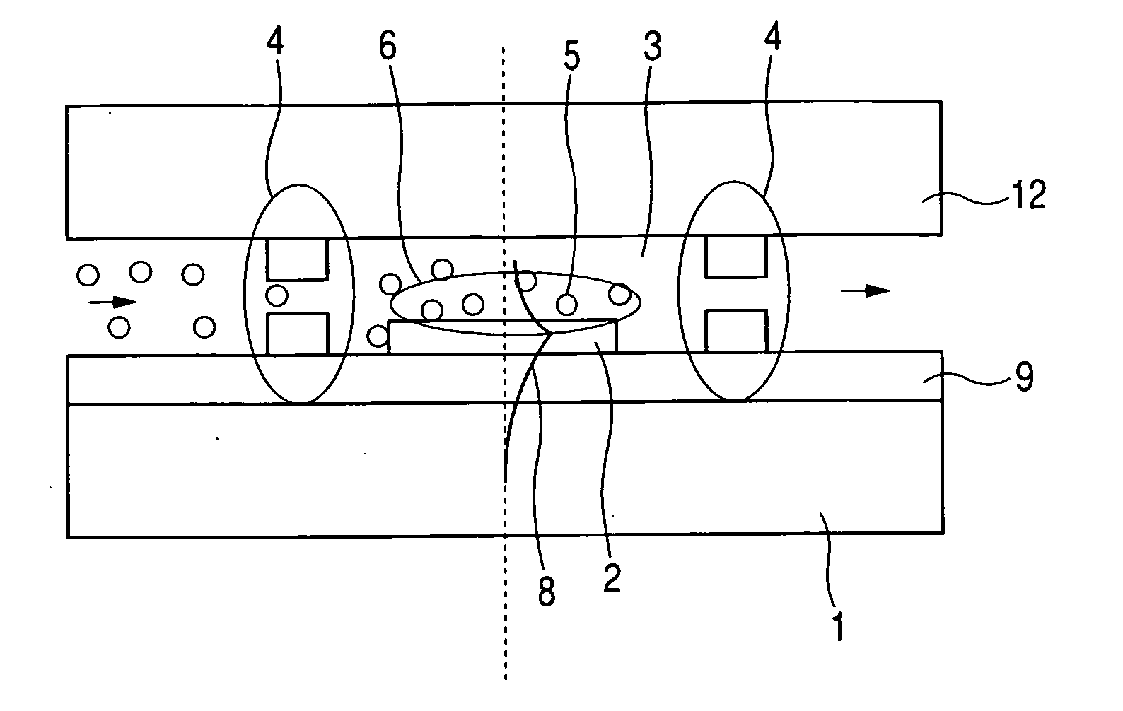
[0037]FIG. 1 is a schematic view showing the feature of a fluid element according to a first embodiment of the present invention. In FIG. 1, reference numeral 1 designates a Si substrate, reference numeral 2 designates a resistor thin film as heating means, reference numeral 3 designates a flow path, reference numeral 5 designates a conceptually shown harmful substance, and reference numeral 6 designates a region of generation of a supercritical state. In addition, reference numeral 4 designates a high inertance flow path, reference numeral 9 designates an SiO2 film, and reference numeral 8 designates a conceptual diagram of temperature distribution when a voltage is applied to the resistor thin film heating means 2.
[0038] That is, the present invention offers an effect in which it is possible to provide a micro fluid element having, within the same substrate, a flow path and a heating means provided in the flow path, and including a function with which a supercri...
second embodiment
(Second Embodiment)
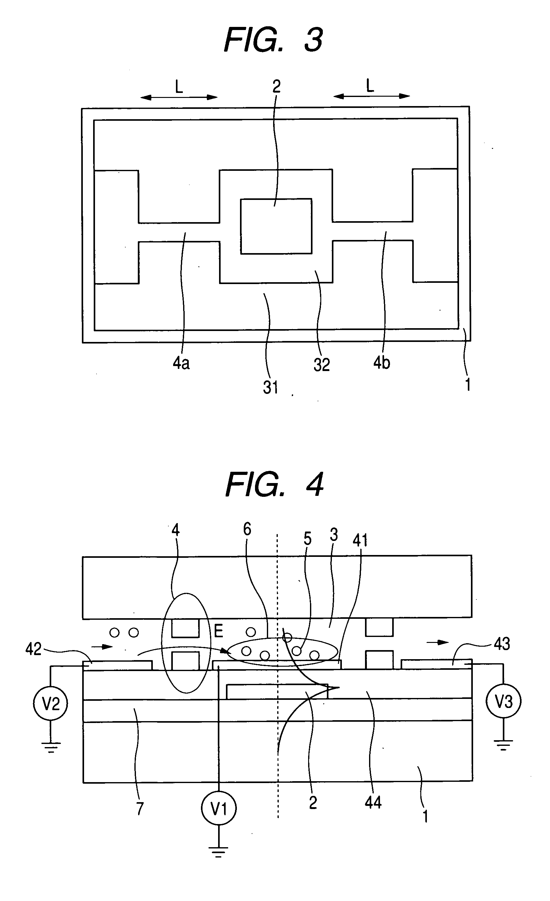
[0060]FIG. 4 is a schematic view showing a fluid element according to a second embodiment of the present invention. In FIG. 4, reference symbols V1, V2, and V3 designate power supplies, respectively, reference numerals 41, 42, and 43 designate first, second, and third electrodes, respectively, and reference numeral 44 designates an SiN insulating thin film with a thickness of 0.3 μm.
[0061] In particular, the fluid element of this embodiment is nearly the same as that of the first embodiment with the exception that the fluid element has the first electrode 41 disposed in the vicinity of the heating means within the flow path and the second electrode 42 disposed within the flow path and that a suitable voltage is applied between the first and the second electrodes 41 and 42 to form an electric field within the flow path to thereby collect an electrolyte in the vicinity of the heating means, and in this state the surface heating is carried out.
[0062] Because there ...
third embodiment
(Third Embodiment)
[0063]FIG. 5 is a schematic view illustrating a feature of a fluid element according to a third embodiment of the present invention. The fluid element of the third embodiment is nearly the same as that of the first embodiment with the exception that each of flow paths 50a and 50b has a flow resistance with which the fluid is easy to flow in a specific direction. Reference numeral 51 designates the specific direction. When each of the flow paths 50a and 50b has the flow resistance with which the fluid is easy to flow in the specific direction 51, a net flow is generated in the specific direction 51 by a pressure generated when a suitable voltage is applied between the electrodes. Thus, there is obtained an effect that a pump function can be exhibited.
PUM
 Abstract
Description
Claims
Application Information