

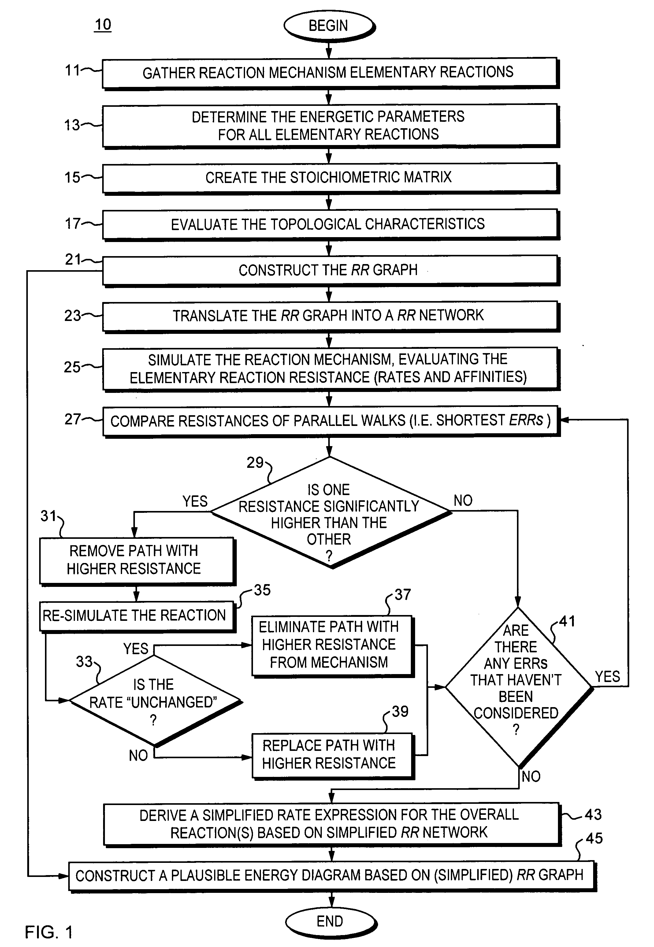
Method and apparatus for reaction route graphs for reaction mechanism and kinetics modeling
Inactive Publication Date: 2005-11-10
VOLTA ENERGY
View PDF1 Cites 7 Cited by
- Summary
- Abstract
- Description
- Claims
- Application Information
AI Technical Summary
Benefits of technology
[0022]FIG. 9 illustrates the Δ-Y transformation of the RR graph to all
Problems solved by technology
However, this is only the first step toward unraveling the mechanism and kinetics of the overall catalytic reactions of interest.
Method used
View moreImage
Smart ImageViewing Examples

Examples
examples
1. Dihydrofolate Reductase (DHFR) System
[0072] The mechanism describing the conversion of 7,8-dihydrofolate (A) and NADPH (B) into 5,6,7,8-tetrahydrofolate (C) and NADP+ (D) as catalyzed by the enzyme dihydrofolate reductase (E) along with a set of rate constants is presented in FIG. 5. The illustrated table is adapted from (Happel, J.; Otarod, M. J. Phys. Chem. B 2000, 104, 5209) This is a single OR of the type
Login to View More PUM
| Property | Measurement | Unit |
|---|---|---|
| Power | aaaaa | aaaaa |
| Mass | aaaaa | aaaaa |
| Electrical resistance | aaaaa | aaaaa |
Abstract
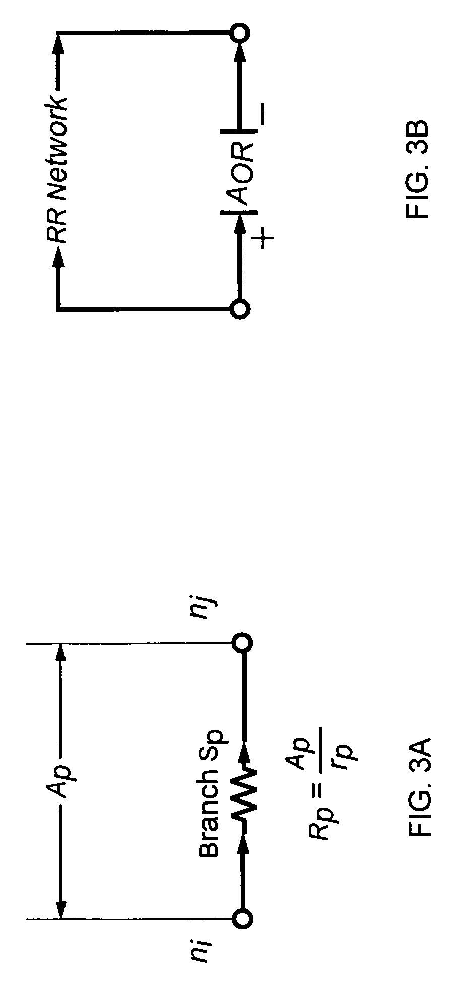
A method and apparatus for reaction route (RR) network analysis is provided in analogy with electrical networks and is based on the combined use of RR theory, graph theory, and Kirchhoff's laws. The result is a powerful new approach of “RR graphs” that is useful in not only topological representation of complex reactions and mechanisms but, when combined with techniques of electrical network analysis, is able to provide revealing insights into the mechanism as well as the kinetics of the overall reactions involving multiple elementary reaction steps including the effect of topological constraints. Unlike existing graph theory approaches of reaction networks, the present invention approach is suitable for linear as well as non-linear kinetic mechanisms and for single and multiple overall reactions. The methodology has broad applicability including atmospheric networks, metabolic networks, and catalytic reaction mechanisms.
Description
RELATED APPLICATION [0001] This application claims the benefit of U.S. Provisional Application No. 60 / 557,295, filed on Mar. 29, 2004. The entire teachings of the above application are incorporated herein by reference.BACKGROUND OF THE INVENTION [0002] This invention relates to the depiction and analysis of reaction mechanisms and kinetics of complex reaction systems in catalysis, biology and chemistry. [0003] Reaction schematics of one kind or another are universally employed to depict reaction pathways in chemistry and cellular biology, and are invaluable in the study of reaction mechanisms. Typically, species, often showing molecular structure, are drawn and interconnected via arrows to show the reactions. Such a scheme, while well-suited for monomolecular reactions, becomes complicated when more than one species is involved in a reaction and especially when there are parallel pathways. [0004] The term “reaction graphs” in the literature alludes to the topology of reaction mechan...
Claims
Login to View More Application Information
Patent Timeline
 IPC IPC(8): C12Q1/68G01N31/00G01N33/48G01N33/50G06F19/00G09B23/24G16B5/20
CPCG06F19/12G06F19/702G09B23/24G16B5/00G16C20/10G16B5/20
InventorFISHTIK, ILIECALLAGHAN, CAITLIN A.DATTA, RAVINDRA
OwnerVOLTA ENERGY