Method of fabricating a cylindrical optical fiber containing a light interactive film

a technology of interactive film and cylindrical optical fiber, which is applied in the field of method of fabricating optical fiber, can solve the problems of difficulty, failure to teach exactly how these fibers are to be fabricated, and related prior art that does not teach a reliable method of fabricating fibers

Inactive Publication Date: 2005-11-17
SYRACUSE UNIVERSITY
View PDF18 Cites 20 Cited by
  • Summary
  • Abstract
  • Description
  • Claims
  • Application Information

AI Technical Summary

Benefits of technology

[0008] Accordingly, it is a primary object of the present invention to provide a fabrication method for optical fibers that includes a light interactive film on the core of the fiber, which ensures continuity of the film along the length of the fiber.
[0014] Another object of the present invention is to provide a fabrication method which employs the use of light interactive coatings in which the viscosity of the particular coating is less than the viscosity of the particular glass at the glass flow point temperature thereby allowing the coating to flow during the fiber drawing process.
[0017] Another object of the present invention is to provide a secondary inorganic coating over the coated “preform” core previously coated with a layer of light interactive material. The object is to prevent a low melting point coating material from dewetting the core at the “preform” collapse temperature.
[0018] These and other objects are accomplished by the method and resulting product of the present invention. The present invention is based upon the observations that during the fiber pulling process, the pressure in the glass can vary by a factor of several thousand from the point where the preform starts to the narrow to the point where the fiber diameter is reached. Consequently, in order for the film layer to maintain continuity, the plaso-viscosity properties of the coating material and the glass must be matched. If the film is pushed along (deformed) by the neighboring glass, which is softer than the film, the front edge of the film is likely to dig in. As a result, the glass might stretch the film beyond its breaking point, thereby tearing the film. Thus, the glass cannot be heated too much or it will be too soft during the drawing process. This makes it necessary to pull the fiber at the lowest temperature possible. Consequently, it is beneficial to conduct the fiber pulling process at temperatures where the film material is in a solid-liquid or liquid phase at the glass softening point. This provides the best assurance that the film will be soft and ductal so that it will deform smoothly when pulled.

Problems solved by technology

The related prior art however, fails to teach exactly how these fibers are to be fabricated when employing a wide variety of coating materials.
However, since the films are relatively thin, difficulty often arises when the fibers are drawn from the ““preform”” as the films tend to fracture and loose their continuity.
The related prior art does not teach a reliable method of fabricating fibers which ensures that the continuity of the film layer is maintained as the fibers are drawn from the “preform”.
That is, the resulting film material only covers portions of the fiber due to breaks in the material.
Moreover, the related art also fails to discuss a method for ensuring that the film layer will remain coherent and homogeneous during the drawing step.

Method used


Image

  • Method of fabricating a cylindrical optical fiber containing a light interactive film
  • Method of fabricating a cylindrical optical fiber containing a light interactive film
  • Method of fabricating a cylindrical optical fiber containing a light interactive film

Examples


example

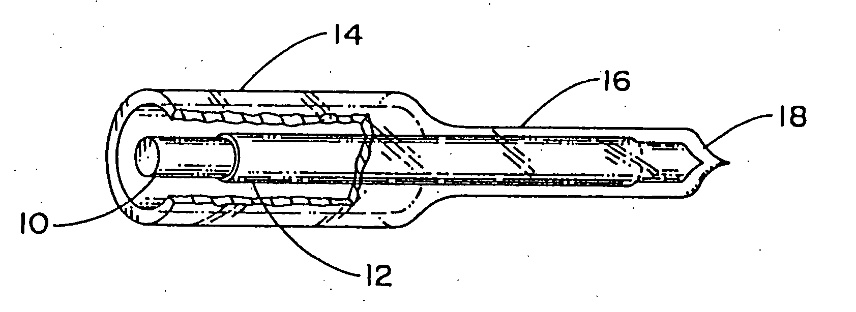
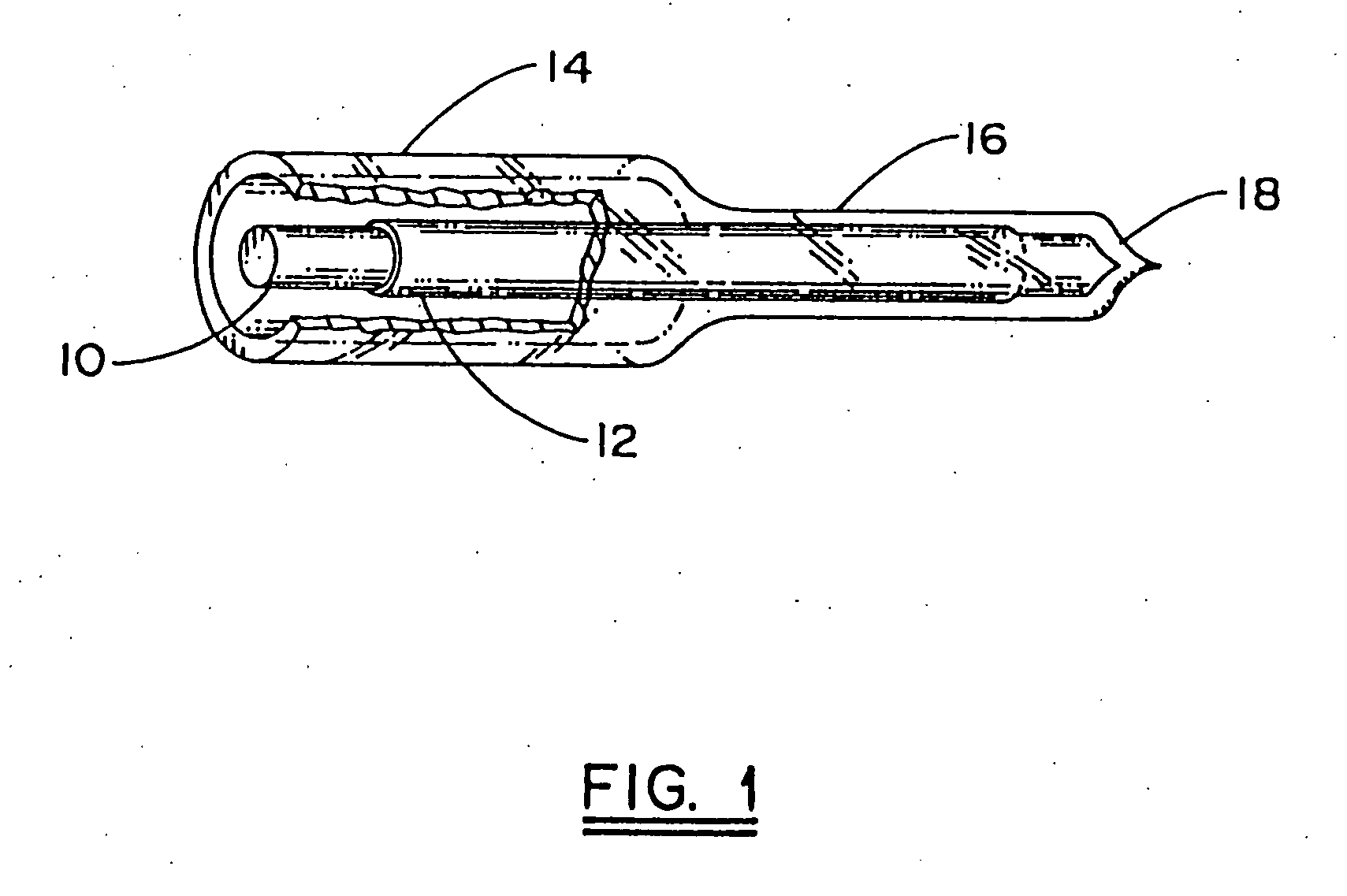
[0053] In one embodiment of the invention an AlCu alloy was used as the coating layer. Cu has a melting point of 1086° C., while Al has a melting point of 660° C. Consequently, the melting point of AlCu can be adjusted by selecting the appropriate Al and Cu composition. Appropriate amounts of Cu and Al are selected to yield the desired alloy. AlCu alloys with melting points ranging from 540° C. to 1084° C. can be fabricated.

[0054] The alloy was vapor deposited on a Corning 7740 glass rod. This rod has a softening point of about 750° C. Consequently, it was necessary to use an alloy which contained between 35 and 100 percent aluminum. Preferably, due to a chemical reaction between the glass and aluminum at the softening point of the glass, higher copper concentrations should be used to reduce evaporation of the alloy. Moreover, alloys that are in the liquid-solid phase are generally acceptable since their viscosity would allow the metal to flow during the fiber drawing process.

[005...


PUM

PropertyMeasurementUnit
diameteraaaaaaaaaa
thicknessaaaaaaaaaa
melting pointaaaaaaaaaa

Abstract

A method of forming a preform which has a glass core surrounded by an outer glass cladding with a coating of a light interactive material disposed between the core and cladding. The method includes providing a glass core having a viscosity which lies within a given preselected temperature range, followed by forming a substantially homogeneous coating of a light interactive material over the surface of the core, with the coating material having a viscosity which is equal to or less than the viscosity of the glass core. A glass cladding is formed over the coated layer, with the cladding glass having a viscosity which overlaps the viscosity of the core glass and a thermal coefficient of expansion compatible with that of the core. The light interactive material is an inorganic material which includes a metal, metal alloy, ferrite, magnetic material and a semiconductor.

Description

CROSS REFERENCE TO RELATED APPLICATIONS [0001] This is a continuation-in-part of U.S. Ser. No. 09 / 934,770, filed Aug. 22, 2001 which is a continuation-in-part of U.S. Ser. No. 09 / 650,368, (now abandoned) filed Aug. 28, 2000, which is a divisional of 09 / 186,189, (now abandoned) filed Nov. 4, 1998, which is a non-provisional of 60 / 090,995, (now abandoned) filed Jun. 29, 1998 the entirety of each of the above applications which are incorporated herein by reference.[0002] This invention was made with government support under Grant No. F30602-96-C-0172 from the U.S. Air Force. Rome Laboratories. The government has certain rights in this invention.FIELD OF THE INVENTION [0003] This invention relates generally to a method of fabricating optical fibers, and more specifically to a method of fabricating optical fibers with a coating of a light interactive material interposed between the cladding and core of the optical fiber. BACKGROUND ART [0004] The technology of fiber optics is constantly ...

Claims


Application Information

Patent Timeline
Patent Type & Authority Applications(United States)
IPC IPC(8): G02B6/00C03B37/012C03B37/026C03B37/027C03C25/10C03C25/42C03C25/46C03C25/52G02B6/02H01S3/06H01S3/067
CPCC03B37/026C03B37/027C03B2201/58C03B2203/10C03B2203/36C03C25/108G02B6/03622C03C25/46C03C25/52G02B6/02G02B6/02214H01S3/06708C03C25/42C03C25/1063
Inventor KORNREICH, PHILIPP G.KELLER, DOUGLAS V. JR.FLATTERY, JAMES
Owner SYRACUSE UNIVERSITY
Why Eureka
Try Eureka