Muffler for compact combustion engines

a technology of compact combustion engine and muffler, which is applied in the direction of engine components, machines/engines, mechanical apparatus, etc., can solve the problems of increasing the temperature of the exhaust gas discharged from the discharge port, inability to provide sufficient cooling, and high temperature unburned components of the exhaust gas, so as to increase the effect of cooling the exhaust gas flowing through

Active Publication Date: 2005-11-17
KAWASAKI MOTORS LTD
View PDF15 Cites 4 Cited by
  • Summary
  • Abstract
  • Description
  • Claims
  • Application Information

AI Technical Summary

Benefits of technology

[0019] Alternatively, the exhaust chamber may be divided by a vertically extending partition wall into an inner upstream compartment and an outer downstream compartment, in which case the exhaust guide passage is positioned within the downstream compartment and represents a g

Problems solved by technology

As is well known, reburning of the exhaust gases in contact with the catalyst results in increase of the temperature of the exhaust gas discharged from a discharge port.
It has, however, been found that the mere use of the auxiliary casing in association with the muffler incorporating a catalytic converter therein, such as disclosed in the above mentioned patent publication is incapable of providing a sufficient cooling effect since the temperature of the exhaust gases is extremely high.
Also, while the wavelength of the pulsating motion of the exhaust gases tends to increase with decrease of the number of revolutions of the combustion engine and the velocity of flow of the exhaust gases is hence lowered, the distance from an outlet of the catalytic converter to the discha

Method used


Image

  • Muffler for compact combustion engines
  • Muffler for compact combustion engines
  • Muffler for compact combustion engines

Examples


Embodiment Construction

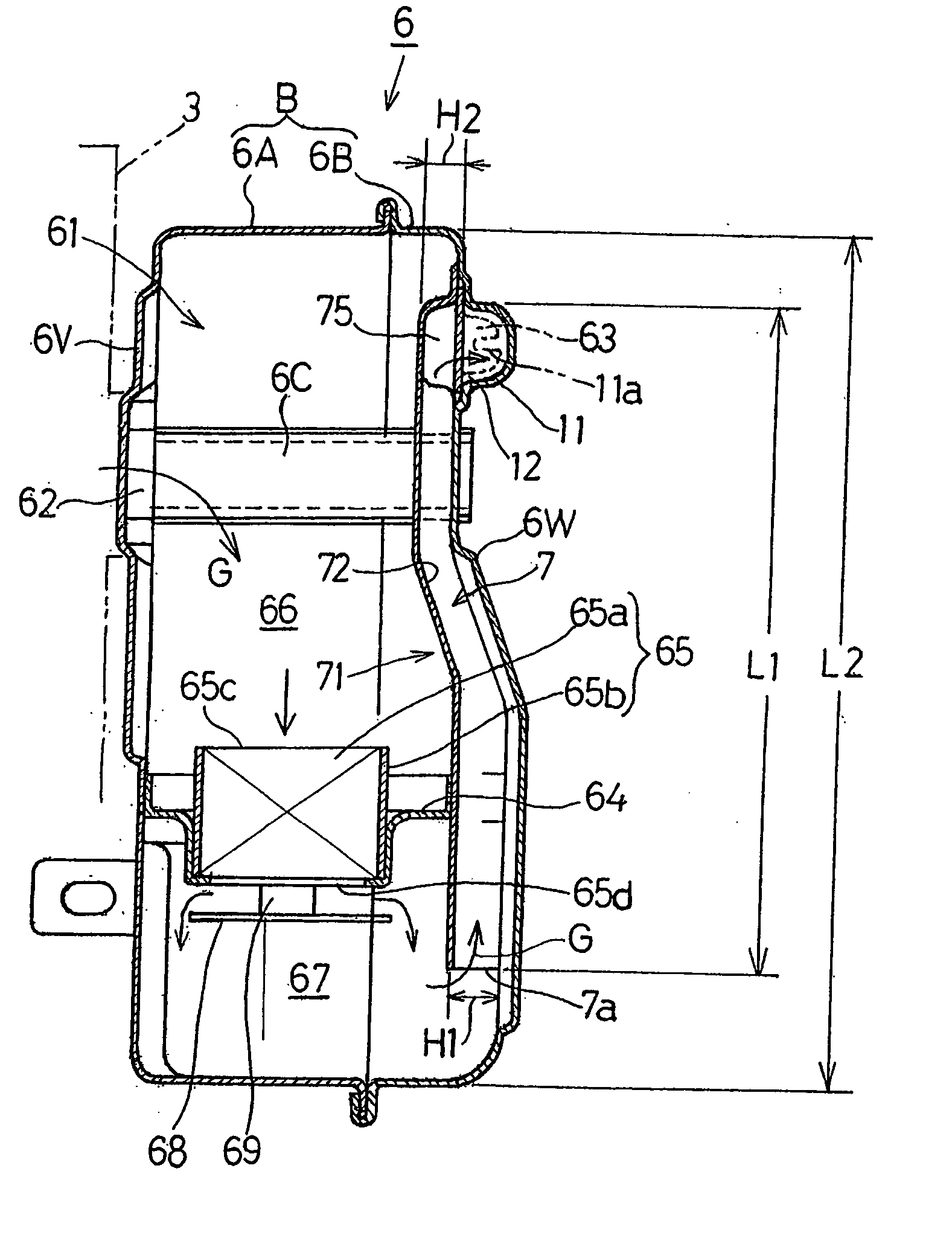
[0034] Hereinafter, preferred embodiments of a muffler for a compact internal combustion engine according to the present invention will be described in detail with reference to the accompanying drawings.

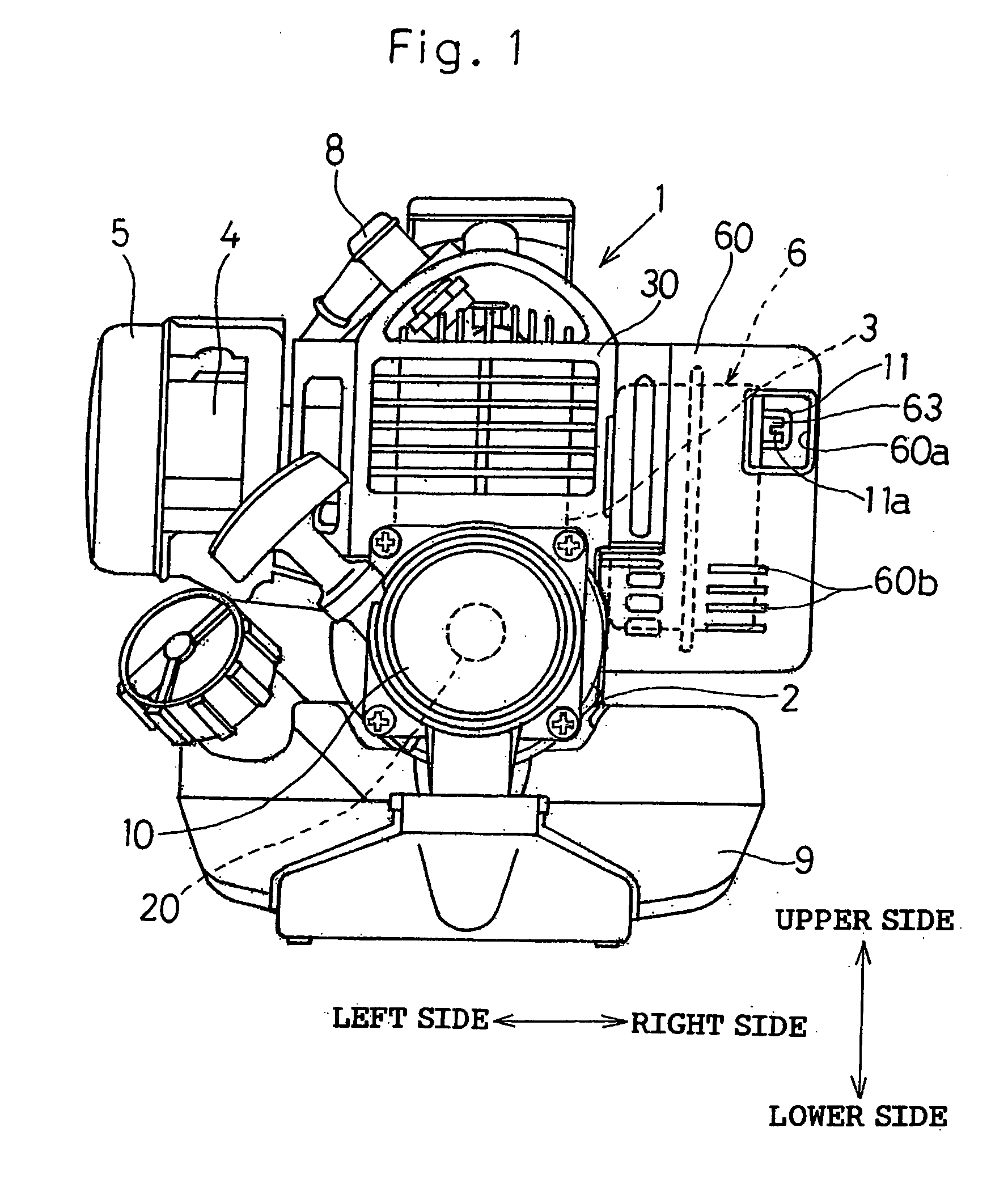
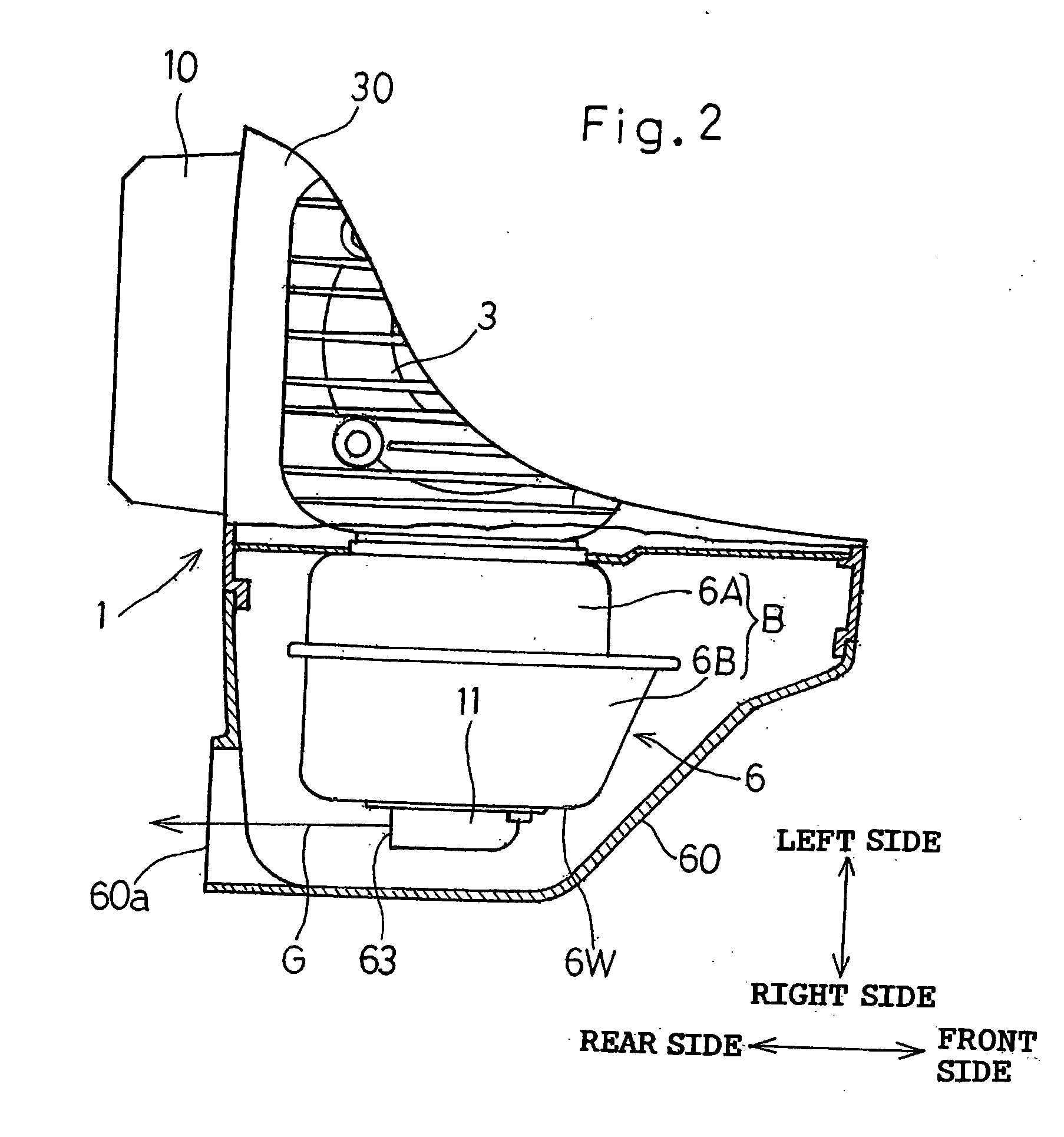
[0035] Referring particularly to FIG. 1, there is shown a rear end view of the compact internal combustion engine equipped with the muffler 6 designed in accordance with a first preferred embodiment of the present invention. As shown therein, the combustion engine, identified generally by 1, includes a crankcase 2, a cylinder block 3 mounted on the crankcase 2, and a crankshaft 20 rotatably supported within the crankcase 2 so as to extend in a direction longitudinally of the combustion engine 1, i.e., in a direction perpendicular to the sheet of FIG. 1. A carburetor 4 and an air cleaner assembly 5 fluidly connected with the carburetor 4 are arranged on a left side, as viewed in FIG. 1, of the cylinder block 3 and the muffler 6 designed in accordance with the present invention is arr...


PUM


Abstract

To provide a muffler for a compact combustion engine, which is simple in structure and effective to sufficiently reduce the temperature of exhaust gases while avoiding contact with an external air, an exhaust guide passage 7 for communicating the exhaust gases (G) to a discharge port (63) is provided within an interior hollow of a muffler housing 6 defining an exhaust chamber (61) therein, and a side wall of this exhaust guide passage (7) is constituted by a portion (6W) of the muffler housing (6) and a duct wall (71) jointed to the muffler housing (6).

Description

BACKGROUND OF THE INVENTION [0001] 1. Field of the Invention [0002] The present invention relates to a muffler for a compact combustion engine used as a drive source in a portable work machine such as, for example, a brush cutting machine or a cleaning blower. [0003] 2. Description of the Prior Art [0004] In this type of engine, it is generally desired to allow the combustion engine to discharge exhaust gases from an exhaust outlet to the outside after the temperature of the exhaust gases has been reduced. [0005] On the other hand, in recent years even the compact combustion engines have come to use an oxidization catalyst for substantially purifying the exhaust gases, specifically reducing respective concentrations of HC and CO contained in the exhaust gases. The oxidization catalyst referred to above is incorporated in a muffler to allow unburned components of the exhaust gases to be reburned in contact with the catalyst. As is well known, reburning of the exhaust gases in contact...

Claims


Application Information

Patent Timeline
IPC IPC(8): F01N1/08F01N3/24F01N13/14F01N13/20
CPCF01N1/084F01N13/002F01N2590/06F01N2230/06F01N2230/04
Inventor KOBAYASHI, MASANORIYUASA, TSUNEYOSHI
Owner KAWASAKI MOTORS LTD
Why Eureka
Try Eureka