
Rotating disk type storage unit with reduced vibration

Inactive Publication Date: 2005-11-17
WESTERN DIGITAL TECH INC
View PDF16 Cites 6 Cited by
  • Summary
  • Abstract
  • Description
  • Claims
  • Application Information

AI Technical Summary

Benefits of technology

[0008] With the magnetic disk apparatus disclosed in Patent Document 1, in order to improve a situation, in which magnetic flux contributing to generation of a thrust moment is decreased at ends of the range of movement of the voice coil to result in reduction in the thrust moment, a length of the magnet in a direction perpendicular to a direction of movement of the voice coil is made long to compensate for a decrease in thrust moment at the ends of the range of movement of the voice coil, thus achieving uniformity of the thrust moment in the range of movement of the voice coil.
[0015] It is a feature of the invention to realize a rotating disk type storage unit, in which bending vibrations and torsional vibrations of a voice coil generated by off-plane vibrational forces on the voice coil are reduced and which enables a large capacity.
[0016] It is a further feature of the invention to realize a rotating disk type storage unit, in which thrust moments of a voice coil motor is made uniform in a range of movement of a voice coil and which enables high-speed access for turning movement of a head at high speed and accurate positioning of the head.
[0023] According to the invention, it is possible to realize a rotating disk type storage unit, in which bending vibrations and torsional vibrations of a voice coil generated by off-plane vibrational forces on the voice coil are reduced and which enables a large capacity.
[0024] Also, according to the invention, it is possible to realize a rotating disk type storage unit, in which thrust moments of a voice coil motor is made uniform in a range of movement of a voice coil and which enables high-speed access for turning movement of a head at high speed and accurate positioning of the head.

Problems solved by technology

Such vibrations make a source that makes noise.
Further, since such vibrations make a factor for obstruction in positioning of a head, there is caused a problem that it becomes difficult to heighten a positional accuracy and so it is not possible to realize a magnetic disk apparatus having a large capacity.
Therefore, the thrust moment is decreased in the vicinity of the magnetic pole changing region of the magnet, or the vicinity of the outer end of the magnet, so that the head disposed at a tip end of the actuator cannot be turningly moved at high speed, and thus high-speed access is made difficult in the magnetic disk apparatus.
Such force makes a force to vibrate the voice coil of the voice coil motor to cause a factor for generation of noise and obstruction in an increase in recording capacity of a magnetic disk apparatus.
That is, Patent Document 1, in which it is intended for compensation for a decrease in thrust moment at the ends of the range of movement of the voice coil, involves a problem that by lengthening the magnet from a central portion to ends in the range of movement of the voice coil, a force to vibrate the voice coil of the voice coil motor is also increased at the ends of the range of movement of the voice coil.

Method used


Image

  • Rotating disk type storage unit with reduced vibration
  • Rotating disk type storage unit with reduced vibration
  • Rotating disk type storage unit with reduced vibration

Examples


first embodiment

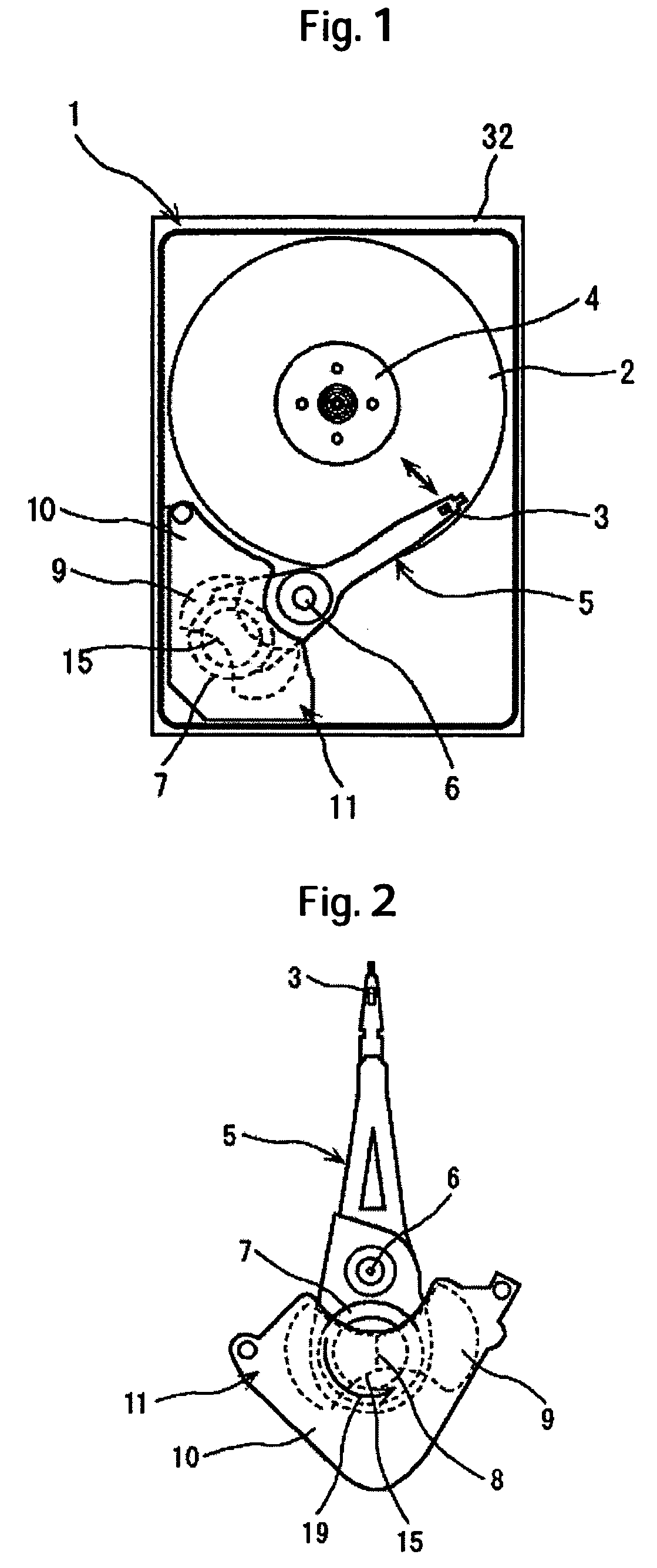
[0037] An entire construction of a magnetic disk apparatus 1 according to the embodiment will be described with reference to FIG. 1. FIG. 1 is a schematic view showing the magnetic disk apparatus according to the

[0038] The magnetic disk apparatus 1 comprises a magnetic disk 2 that constitutes a rotating disk recording medium, a magnetic head 3 that moves radially relative to the magnetic disk 2 to perform recording or reproduction, a turnable actuator 5 mounting on one side thereof the magnetic head 3 and having a turning shaft 61, and a voice coil motor 11 to drive the actuator 5. The magnetic disk apparatus 1 is provided with a base 32 and a cover (not shown) of a disk enclosure, the base 32 being formed by die casting of aluminum, or press working of steel sheet such as stainless steel or the like.

[0039] The magnetic disk 2 is mounted at a center thereof to a spindle motor 4, which serves as a drive source, and arranged substantially in parallel with a bottom surface of the base...

second embodiment

[0059] magnets 9 having a pair of magnetic pole portions of different polarities are arranged symmetrically to be in parallel with a voice coil 7 and in opposition to each other vertically. Thereby, it is possible to further decrease forces, which cause vibrations in an off-plane direction.

[0060] In addition, the invention is not limited to the embodiments disclosed above but allows modifications based on a prior art.

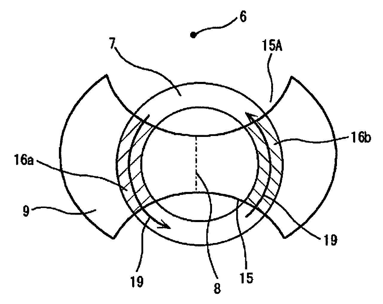
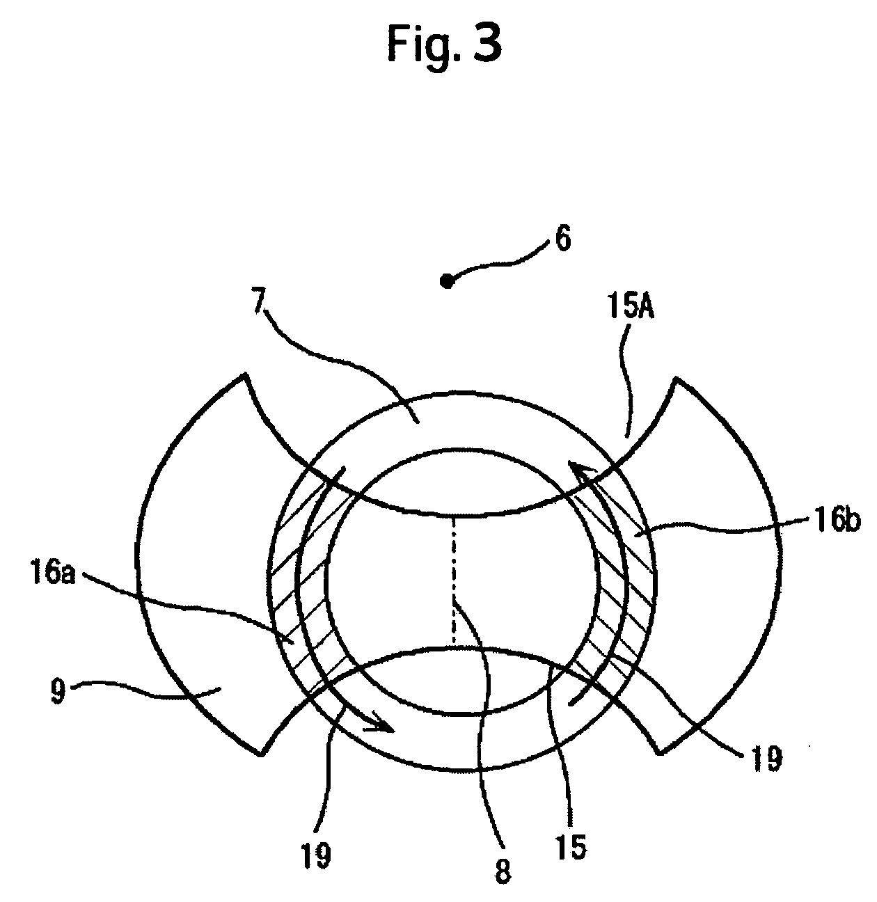
[0061] Subsequently, a third embodiment of the invention will be described with reference to FIGS. 6 and 7. FIG. 6 is a plan view showing an actuator provided with a voice coil motor of a magnetic disk apparatus according to the third embodiment of the invention, and FIG. 7 is an enlarged plan view showing the voice coil and a magnet in the voice coil motor shown in FIG. 6. The third embodiment is different from the first embodiment as described below, and fundamentally the same as the first embodiment in other respects.

[0062] A magnetic disk 2 has a smooth surface, ...


PUM


Abstract

Embodiments of the invention decrease bending vibrations and torsional vibrations of a voice coil generated by off-plane vibrational forces on the voice coil to reduce noise and to enable a large capacity. In one embodiment, a rotating disk type storage unit comprises a rotating disk recording medium, a head that moves radially relative to the rotating disk recording medium to perform recording or reproduction, a turnable actuator having mounted on one side thereof the head, and a voice coil motor to drive the actuator. The voice coil motor comprises a voice coil mounted on the other side end of the actuator, and a magnet arranged in opposition to the voice coil. A magnet outer periphery of the magnet disposed distant from an actuator turning center is formed to be arcuately concave in shape, and the concave-shaped outer periphery intersects the voice coil.

Description

CROSS-REFERENCES TO RELATED APPLICATIONS [0001] This application claims priority from Japanese Patent Application No. JP2004-145976, filed May 17, 2004, the entire disclosure of which is incorporated herein by reference. BACKGROUND OF THE INVENTION [0002] The present invention relates to a rotating disk type storage unit, and is suited to a rotating disk type storage unit, in which a voice coil motor drives an actuator mounting thereon a head. [0003] A magnetic disk apparatus exemplary of a rotating disk type storage unit drives an actuator mounting thereon a magnetic head to thereby position the magnetic head that performs recording or reproduction of information on a magnetic disk. Used as a drive source for the actuator is a voice coil motor comprising a voice coil mounted on one end of the actuator, a magnet arranged in opposition to the voice coil, and a voice yoke member that forms a magnetic circuit. A thrust moment of the actuator is obtained from electric current applied to...

Claims


Application Information

Patent Timeline
IPC IPC(8): G11B21/02G11B5/54G11B5/55G11B5/56G11B5/596G11B21/08G11B21/22H02K33/18
CPCG11B5/56G11B5/5565
Inventor SUZUKI, KENJISHIMIZU, TOSHIHIKOTSUDA, SHINGOUEFUNE, KOUKI
Owner WESTERN DIGITAL TECH INC
Features
  • Generate Ideas
  • Intellectual Property
  • Life Sciences
  • Materials
  • Tech Scout
  • Unparalleled Data Quality
  • Higher Quality Content
  • 60% Fewer Hallucinations
Learn More